Cirkit Designer
Your all-in-one circuit design IDE
Home /
Component Documentation
How to Use n20 motor with encoder: Examples, Pinouts, and Specs
Introduction
The N20 Motor with Encoder is a compact DC gearmotor featuring a built-in quadrature encoder that provides feedback on the motor's rotational position or speed. This motor is widely used in robotics, precision motion control, and hobbyist projects due to its small size, low power consumption, and precise control capabilities.
Explore Projects Built with n20 motor with encoder
ESP32-Based Wi-Fi Controlled Robotic System with Multiple Sensors and Motor Drivers
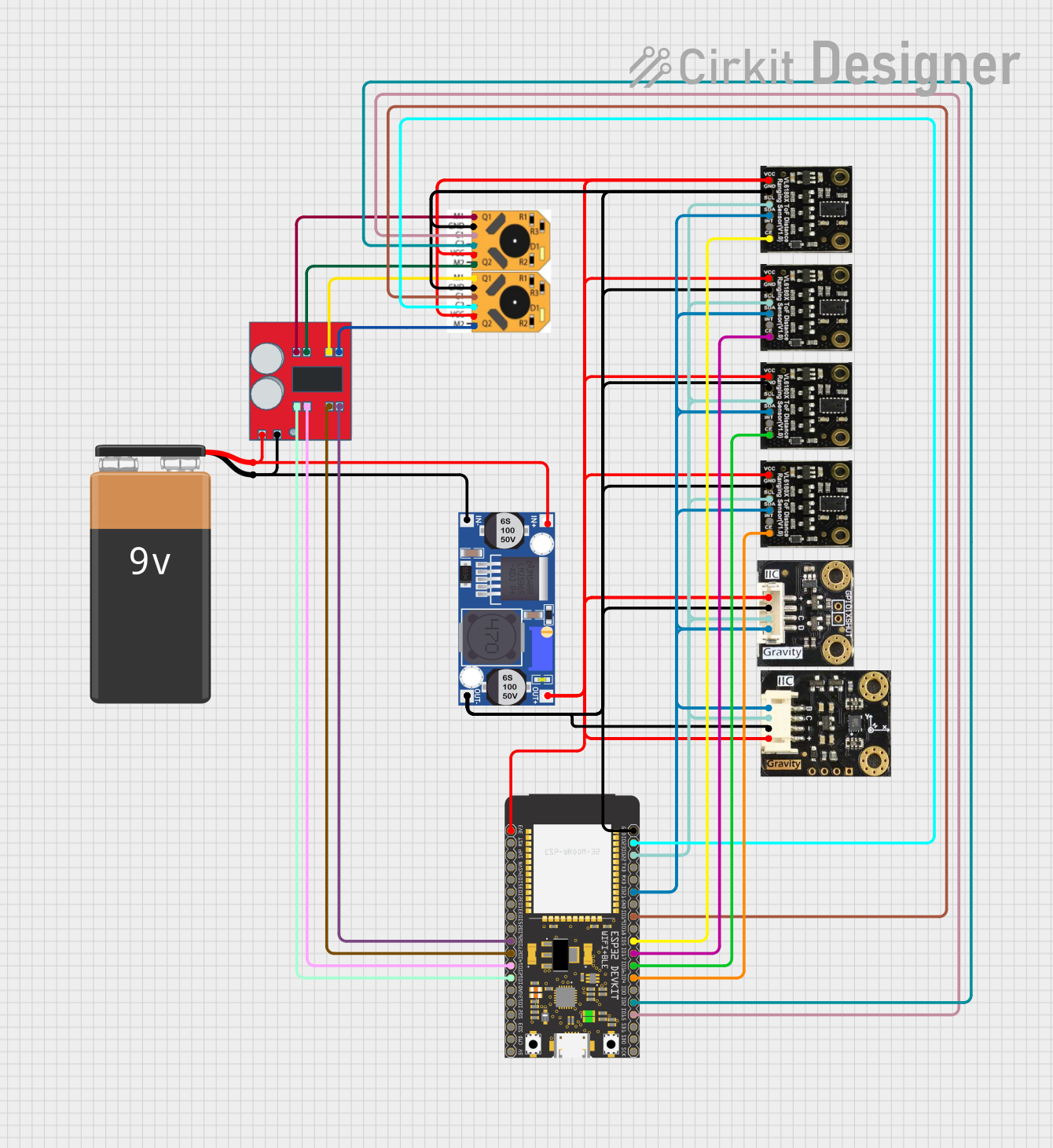
This circuit is a sensor and motor control system powered by a 9V battery and regulated by a buck converter. It includes multiple sensors (SEN0245, SEN0427, I2C BMI160) connected via I2C to an ESP32 microcontroller, which also controls two N20 motors with encoders through an MX1508 DC motor driver.
Arduino-Controlled DC Motor with Encoder Feedback and Adjustable Speed

This circuit controls a gear motor with an integrated encoder using an L298N DC motor driver, which is interfaced with an Arduino Mega 2560 microcontroller. The motor's power is supplied by a 12V power source, which is also connected to an XL4015 DC Buck Step-down converter to provide a regulated 5V supply to the Arduino. The encoder outputs are connected to the Arduino for position or speed feedback, and the Arduino is programmed to manage the motor's speed and direction.
Arduino Nano Controlled DC Motor with Encoder for Precise Movement
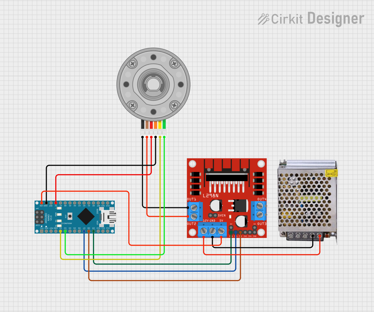
This circuit controls a DC motor with an encoder using an Arduino Nano and an L298N motor driver. The Arduino Nano reads the encoder signals to track the motor's position and controls the motor's direction and speed through the L298N driver, powered by a 12V power supply.
STM32F407-Controlled Robotic System with Touch Interface and Motor Actuation
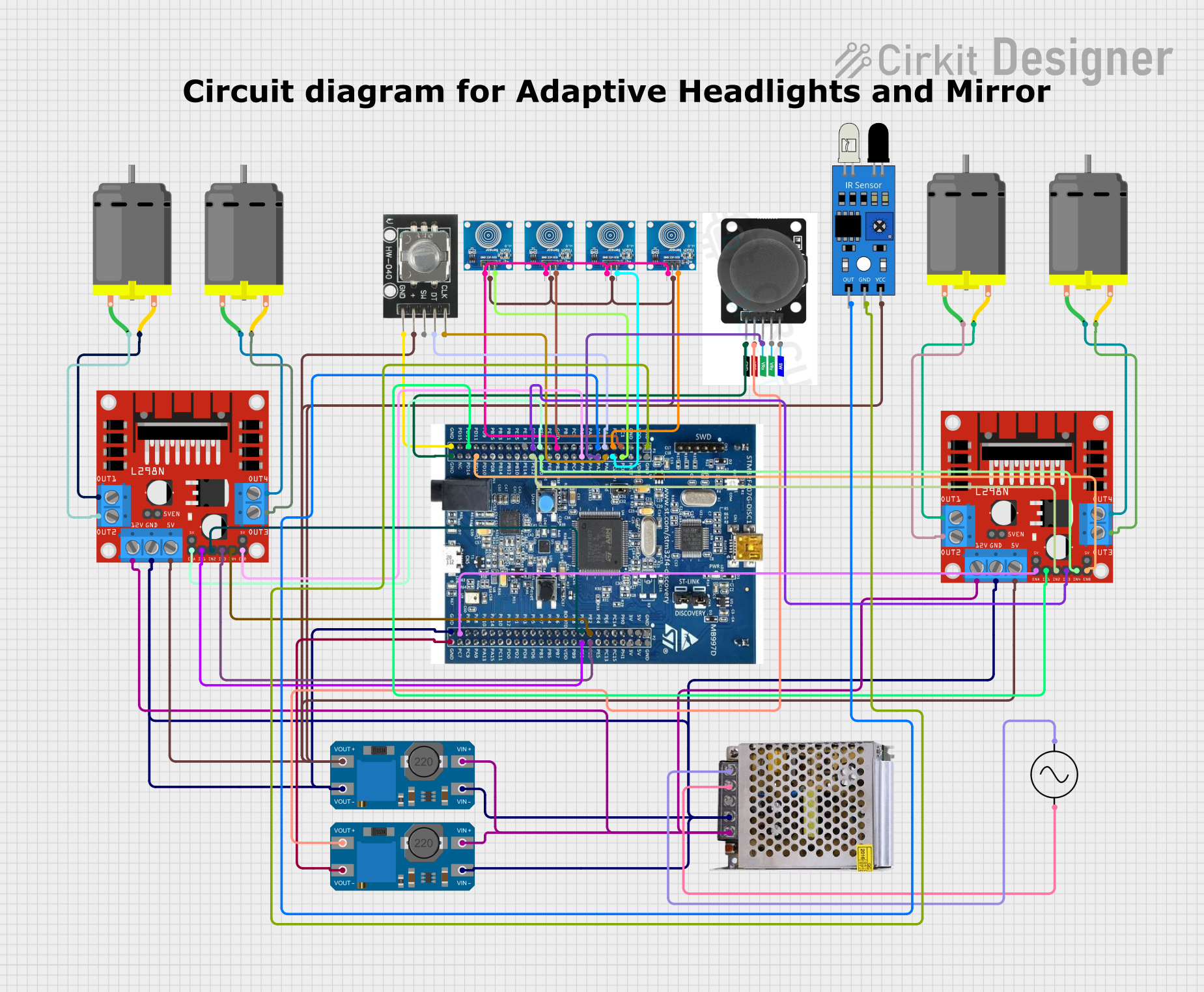
This circuit is designed to control multiple DC motors using L298N motor drivers, which are interfaced with an STM32F407 Discovery Kit microcontroller. The microcontroller receives input from a rotary encoder, multiple touch sensors, a joystick module, and an IR sensor to determine the motors' behavior. A 12V power supply provides power to the motor drivers, which is regulated for other components by MT3608 step-up converters, and the entire system is powered by an AC supply connected to the 12V power supply unit.
Explore Projects Built with n20 motor with encoder
ESP32-Based Wi-Fi Controlled Robotic System with Multiple Sensors and Motor Drivers
This circuit is a sensor and motor control system powered by a 9V battery and regulated by a buck converter. It includes multiple sensors (SEN0245, SEN0427, I2C BMI160) connected via I2C to an ESP32 microcontroller, which also controls two N20 motors with encoders through an MX1508 DC motor driver.
Arduino-Controlled DC Motor with Encoder Feedback and Adjustable Speed
This circuit controls a gear motor with an integrated encoder using an L298N DC motor driver, which is interfaced with an Arduino Mega 2560 microcontroller. The motor's power is supplied by a 12V power source, which is also connected to an XL4015 DC Buck Step-down converter to provide a regulated 5V supply to the Arduino. The encoder outputs are connected to the Arduino for position or speed feedback, and the Arduino is programmed to manage the motor's speed and direction.
Arduino Nano Controlled DC Motor with Encoder for Precise Movement
This circuit controls a DC motor with an encoder using an Arduino Nano and an L298N motor driver. The Arduino Nano reads the encoder signals to track the motor's position and controls the motor's direction and speed through the L298N driver, powered by a 12V power supply.
STM32F407-Controlled Robotic System with Touch Interface and Motor Actuation
This circuit is designed to control multiple DC motors using L298N motor drivers, which are interfaced with an STM32F407 Discovery Kit microcontroller. The microcontroller receives input from a rotary encoder, multiple touch sensors, a joystick module, and an IR sensor to determine the motors' behavior. A 12V power supply provides power to the motor drivers, which is regulated for other components by MT3608 step-up converters, and the entire system is powered by an AC supply connected to the 12V power supply unit.
Common Applications and Use Cases
- Robotic arms and grippers
- Automated guided vehicles (AGVs)
- Precision positioning systems
- Hobbyist projects requiring motor feedback
Technical Specifications
Key Technical Details
- Voltage Range: Typically 3V to 12V DC
- No-Load Speed: Varies with voltage, often around 100 RPM at 6V
- Stall Torque: Varies with voltage, often around 1 to 2 kg-cm at 6V
- Gear Ratio: Typically ranges from 30:1 to 1000:1
- Encoder Resolution: Often 11 pulses per revolution (PPR) per channel, varies by model
Pin Configuration and Descriptions
| Pin Number | Description | Notes |
|---|---|---|
| 1 | Motor Power (+) | Connect to positive voltage |
| 2 | Motor Power (-) | Connect to ground |
| 3 | Encoder Output A | Quadrature encoder output A |
| 4 | Encoder Output B | Quadrature encoder output B |
| 5 | Encoder Vcc (optional) | Encoder power supply (if separate from motor power) |
| 6 | Encoder GND (optional) | Encoder ground (if separate from motor power) |
Usage Instructions
How to Use the Component in a Circuit
- Power Connections: Connect the motor power pins to your power source, ensuring that the voltage is within the motor's specified range.
- Encoder Connections: Connect the encoder outputs to your microcontroller or other devices capable of reading digital signals.
- Optional Encoder Power: If the encoder operates at a different voltage than the motor, connect the encoder Vcc and GND to the appropriate power supply.
Important Considerations and Best Practices
- Voltage Limits: Do not exceed the recommended voltage range to avoid damaging the motor.
- Current Draw: Be aware of the motor's current draw, especially at stall, to select an appropriate driver.
- Interference: Keep encoder signal lines away from high-power lines to minimize electrical noise.
- Mounting: Secure the motor firmly to prevent vibrations and ensure accurate encoder readings.
Example Arduino Code
// Example code for controlling an N20 Motor with Encoder using an Arduino UNO

const int motorPin1 = 3; // Motor power pin connected to Arduino pin 3 (PWM capable)
const int motorPin2 = 4; // Motor power pin connected to Arduino pin 4
const int encoderPinA = 2; // Encoder output A connected to Arduino pin 2
const int encoderPinB = 5; // Encoder output B connected to Arduino pin 5

volatile long encoderCount = 0; // Variable to store encoder count

// Interrupt service routine for encoder A
void encoderISR() {
  if (digitalRead(encoderPinA) == digitalRead(encoderPinB)) {
    encoderCount++;
  } else {
    encoderCount--;
  }
}

void setup() {
  pinMode(motorPin1, OUTPUT);
  pinMode(motorPin2, OUTPUT);
  pinMode(encoderPinA, INPUT);
  pinMode(encoderPinB, INPUT);

  // Attach interrupt for encoder pin A (interrupt 0 is pin 2 on UNO)
  attachInterrupt(digitalPinToInterrupt(encoderPinA), encoderISR, CHANGE);
}

void loop() {
  // Set motor direction and speed
  analogWrite(motorPin1, 128); // Set speed (0-255)
  digitalWrite(motorPin2, LOW); // Set direction

  // Do something with the encoder count
  // For example, stop the motor after a certain number of counts
  if (encoderCount > 1000) {
    analogWrite(motorPin1, 0); // Stop the motor
    // Reset the encoder count for the next run
    encoderCount = 0;
  }
}
Troubleshooting and FAQs
Common Issues Users Might Face
- Motor does not turn: Check power supply and wiring connections.
- Inaccurate encoder readings: Ensure that the encoder pins are not picking up noise and that the motor is mounted securely.
- Motor turns but no encoder signal: Verify that the encoder pins are connected correctly and that the microcontroller is configured to read the encoder signals.
Solutions and Tips for Troubleshooting
- Power Supply: Use a multimeter to verify that the power supply is delivering the correct voltage.
- Wiring: Double-check all connections, including solder joints and breadboard connections.
- Signal Integrity: Use shielded cables for encoder signals and keep them away from power wires.
- Debouncing: Implement software debouncing if encoder signals are noisy.
FAQs
- Q: Can I run the motor at a higher voltage for more speed?
- A: Running the motor beyond its rated voltage can lead to overheating and damage. Stick to the recommended voltage range.
- Q: How do I reverse the motor's direction?
- A: Reverse the polarity of the motor power connections.
- Q: What is the maximum encoder frequency the Arduino can handle?
- A: This depends on the specific Arduino model and the rest of your code. For UNO, it's typically safe to read frequencies up to a few kHz.
Remember to adjust the example code to fit the specific technical specifications of your N20 motor with encoder, as these can vary between models and manufacturers.