How to Use Resistor: Examples, Pinouts, and Specs
Introduction
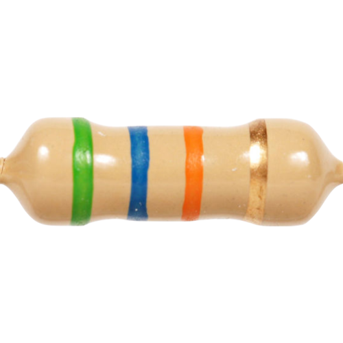
A resistor is a fundamental passive electronic component widely used in electrical and electronic circuits. Its primary function is to limit or regulate the flow of electric current to a desired level. By providing resistance, it can control the amount of current, divide voltages across components, and establish proper operating conditions for various circuit elements. Resistors are essential in applications ranging from simple LED circuits to complex computer systems.
Explore Projects Built with Resistor
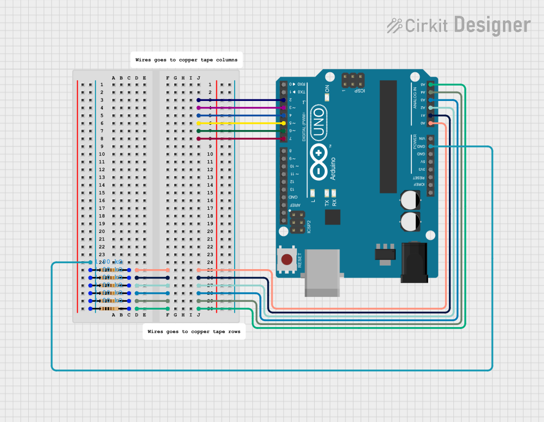
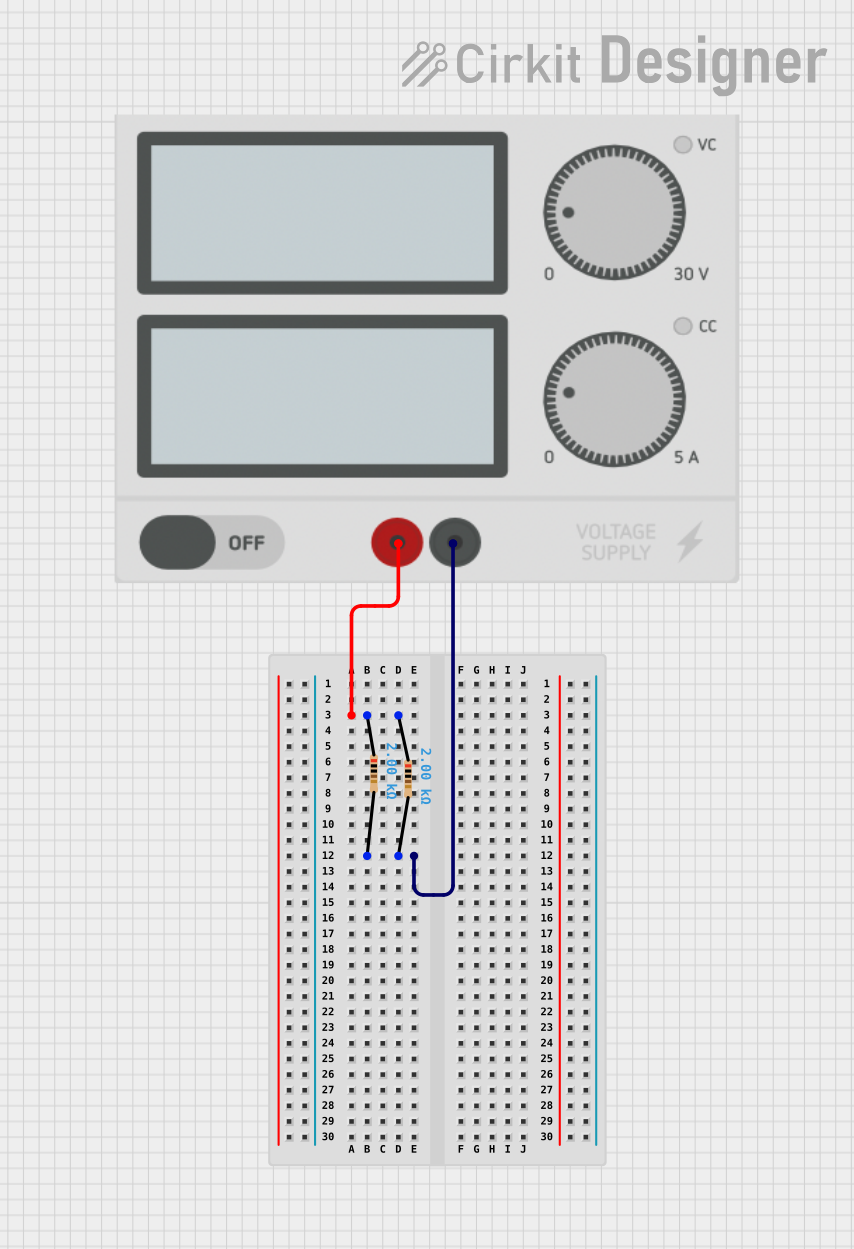
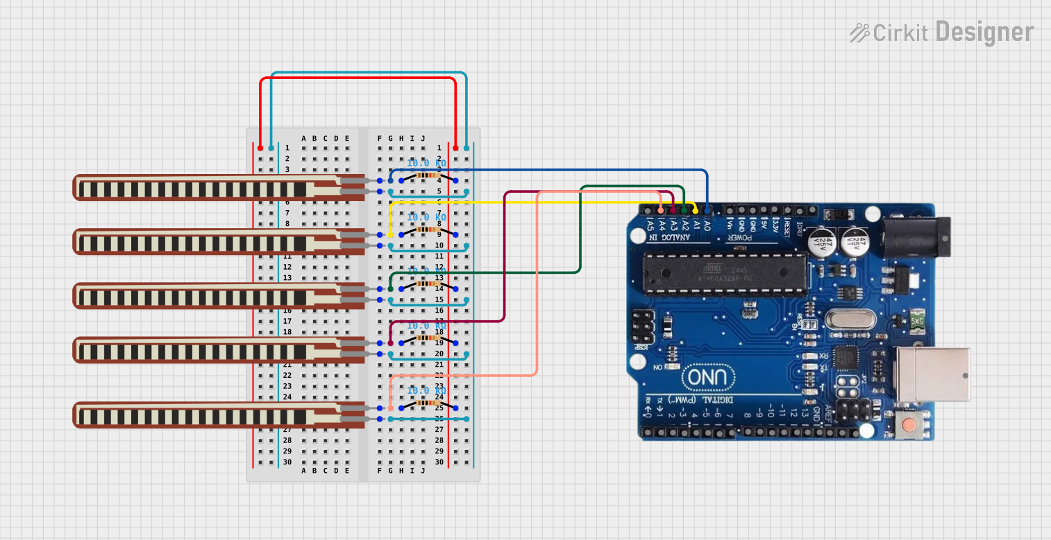
Explore Projects Built with Resistor
Common Applications and Use Cases
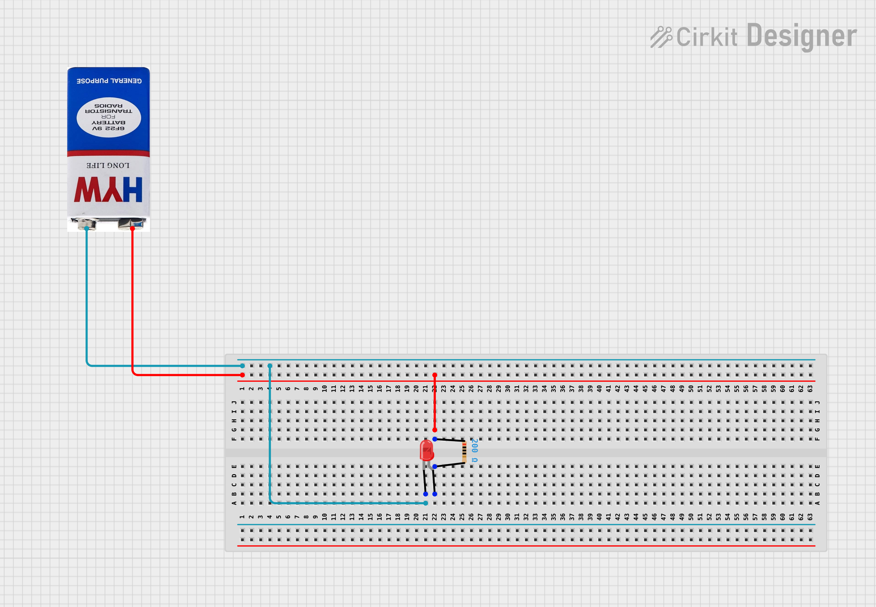
- Limiting current to LEDs and other sensitive components
- Pull-up and pull-down resistors for logic circuits
- Voltage division in analog circuits
- Load resistors in power supplies and amplifiers
- Biasing active components like transistors
- Filtering signals in conjunction with capacitors and inductors
Technical Specifications
Key Technical Details
- Resistance (R): The opposition to current flow, measured in ohms (Ω).
- Power Rating (P): The maximum power the resistor can dissipate without damage, measured in watts (W).
- Tolerance: The precision of the resistance value, expressed as a percentage (e.g., ±1%).
- Temperature Coefficient: The rate at which the resistance value changes with temperature.
Pin Configuration and Descriptions
Resistors are typically two-terminal components with no polarity, meaning they can be connected in any direction. However, some specialized resistors like varistors or thermistors may have specific configurations or considerations.
| Pin | Description |
|---|---|
| 1 | Terminal A |
| 2 | Terminal B |
Usage Instructions
How to Use the Resistor in a Circuit
- Determine the Required Resistance: Use Ohm's law (V = IR) and other circuit design principles to calculate the necessary resistance for your application.
- Select the Resistor: Choose a resistor with the appropriate resistance value and power rating. Ensure the tolerance is suitable for your circuit's precision needs.
- Insert the Resistor: Place the resistor in the circuit. For breadboard or prototyping, insert each lead into a separate hole. For soldering, ensure a good mechanical and electrical connection.
Important Considerations and Best Practices
- Power Dissipation: Ensure the resistor's power rating exceeds the expected power dissipation to prevent overheating and damage.
- Tolerance Matching: For precision circuits, select resistors with tighter tolerance to minimize variance.
- Temperature Effects: Be aware of the temperature coefficient if the resistor will operate in varying temperatures.
- Series and Parallel Configurations: Use series connections to add resistances and parallel connections to create a lower equivalent resistance.
Troubleshooting and FAQs
Common Issues Users Might Face
- Excessive Heat: If a resistor is too hot, it may be dissipating more power than its rating allows. Check the circuit for excessive current and replace the resistor with one of a higher power rating if necessary.
- Unexpected Voltage Drops: Incorrect resistance values can lead to unexpected voltage drops. Verify the resistor's value with a multimeter and replace it if it's out of tolerance.
- Open Circuit: A damaged or poorly connected resistor can cause an open circuit. Inspect the resistor for physical damage and ensure proper connection.
Solutions and Tips for Troubleshooting
- Use a Multimeter: Measure the resistance to ensure it matches the expected value. Check for continuity to rule out an open circuit.
- Check Circuit Design: Re-evaluate the circuit design to confirm the correct resistor values and configurations are used.
- Inspect for Physical Damage: Look for signs of burning, cracking, or discoloration on the resistor, which indicate damage.
FAQs
Q: Can I replace a resistor with a higher power rating?
A: Yes, as long as the resistance value is the same, a higher power rating is generally acceptable and can offer better reliability.
Q: What happens if I use a resistor with a lower resistance value than required?
A: Using a lower resistance value will allow more current to flow through the circuit, which could damage other components or alter the circuit's performance.
Q: How do I connect a resistor to an Arduino UNO?
A: Connect one terminal of the resistor to an Arduino I/O pin and the other to the component you wish to interface with the Arduino, such as an LED. Ensure you calculate the required resistance to prevent damage to the LED or the Arduino pin.
Example Arduino Code for Using a Resistor with an LED
// Define the Arduino pin connected to the LED (with a series resistor)
const int ledPin = 13;

void setup() {
  // Set the LED pin as an output
  pinMode(ledPin, OUTPUT);
}

void loop() {
  // Turn the LED on
  digitalWrite(ledPin, HIGH);
  delay(1000); // Wait for 1 second
  // Turn the LED off
  digitalWrite(ledPin, LOW);
  delay(1000); // Wait for 1 second
}
Note: The above code assumes the use of a current-limiting resistor in series with the LED connected to pin 13. The value of the resistor should be calculated based on the LED's specifications and the supply voltage.