How to Use LM2596 Buck Convertor Step Down: Examples, Pinouts, and Specs
Introduction
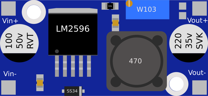
The LM2596 is a step-down (buck) voltage regulator designed to efficiently convert a higher input voltage to a lower output voltage. It is widely used in power supply applications due to its high efficiency, ease of use, and robust protection features. The LM2596 can handle up to 3A of output current and includes built-in thermal shutdown and current limiting to safeguard the circuit.
Explore Projects Built with LM2596 Buck Convertor Step Down


Explore Projects Built with LM2596 Buck Convertor Step Down
Common Applications and Use Cases
- DC-DC voltage regulation in power supply circuits
- Battery-powered devices requiring stable voltage
- LED drivers and lighting systems
- Embedded systems and microcontroller-based projects
- Industrial automation and control systems
Technical Specifications
Key Technical Details
| Parameter | Value |
|---|---|
| Input Voltage Range | 4.5V to 40V |
| Output Voltage Range | 1.23V to 37V (adjustable) |
| Maximum Output Current | 3A |
| Efficiency | Up to 92% |
| Switching Frequency | 150 kHz |
| Output Voltage Accuracy | ±4% |
| Thermal Shutdown | Yes |
| Current Limiting | Yes |
| Package Type | TO-220, TO-263 |
Pin Configuration and Descriptions
| Pin Number | Pin Name | Description |
|---|---|---|
| 1 | VIN | Input voltage pin (4.5V to 40V) |
| 2 | VOUT | Regulated output voltage pin (1.23V to 37V) |
| 3 | GND | Ground pin |
| 4 | FB (Feedback) | Feedback pin for output voltage adjustment |
| 5 | ON/OFF | Enable/disable pin (optional, active low) |
Usage Instructions
How to Use the LM2596 in a Circuit
- Input Voltage: Connect the input voltage (VIN) to the LM2596. Ensure the input voltage is within the range of 4.5V to 40V.
- Output Voltage Adjustment: Use a voltage divider circuit connected to the FB (Feedback) pin to set the desired output voltage. The formula for output voltage is: [ V_{OUT} = V_{REF} \times \left(1 + \frac{R1}{R2}\right) ] where ( V_{REF} ) is 1.23V.
- Output Capacitor: Place a suitable capacitor (e.g., 100µF) at the output to stabilize the voltage.
- Input Capacitor: Add a capacitor (e.g., 47µF) at the input to filter noise and improve stability.
- Inductor Selection: Choose an inductor with appropriate current rating and inductance value (e.g., 33µH) based on your application.
- Enable Pin: If using the ON/OFF pin, connect it to GND to enable the regulator or leave it floating for continuous operation.
Important Considerations and Best Practices
- Heat Dissipation: Use a heatsink if the LM2596 operates at high currents to prevent overheating.
- PCB Layout: Minimize the length of high-current paths and place capacitors close to the pins to reduce noise.
- Load Regulation: Ensure the load does not exceed the maximum current rating of 3A.
- Arduino Compatibility: The LM2596 can be used to power Arduino boards by stepping down a higher voltage (e.g., 12V) to 5V or 3.3V.
Example: Using LM2596 with Arduino UNO
The following example demonstrates how to use the LM2596 to power an Arduino UNO with a 12V input:
Circuit Connections
- Connect the 12V input to the VIN pin of the LM2596.
- Adjust the output voltage to 5V using the feedback pin and a multimeter.
- Connect the VOUT pin to the Arduino UNO's 5V pin.
- Connect the GND pin of the LM2596 to the Arduino's GND.
Arduino Code Example
// Example code to blink an LED using Arduino UNO powered by LM2596
// Ensure the LM2596 output is set to 5V before connecting to Arduino

const int ledPin = 13; // Built-in LED pin on Arduino UNO

void setup() {
  pinMode(ledPin, OUTPUT); // Set LED pin as output
}

void loop() {
  digitalWrite(ledPin, HIGH); // Turn the LED on
  delay(1000);                // Wait for 1 second
  digitalWrite(ledPin, LOW);  // Turn the LED off
  delay(1000);                // Wait for 1 second
}
Troubleshooting and FAQs
Common Issues and Solutions
No Output Voltage:
- Check the input voltage; ensure it is within the specified range (4.5V to 40V).
- Verify the feedback resistor values and connections.
- Ensure the ON/OFF pin is not pulled low (if used).
Overheating:
- Use a heatsink to dissipate heat.
- Reduce the load current if it exceeds 3A.
- Ensure proper ventilation around the component.
Output Voltage Instability:
- Check the input and output capacitors; replace them if faulty.
- Ensure the inductor value is appropriate for the load.
Low Efficiency:
- Verify that the input voltage is not excessively higher than the output voltage.
- Use low-ESR capacitors for better performance.
FAQs
Q1: Can the LM2596 be used to power a Raspberry Pi?
A1: Yes, the LM2596 can step down a higher voltage (e.g., 12V) to 5V to power a Raspberry Pi. Ensure the output current is sufficient for the Raspberry Pi model in use.
Q2: How do I adjust the output voltage?
A2: Use a potentiometer or a fixed resistor divider network connected to the FB pin. Measure the output voltage with a multimeter and adjust as needed.
Q3: What happens if the load exceeds 3A?
A3: The LM2596 includes current limiting protection, which will reduce the output current to prevent damage. However, prolonged overcurrent conditions may cause overheating.
Q4: Can I use the LM2596 for AC to DC conversion?
A4: No, the LM2596 is a DC-DC converter. Use a rectifier and filter circuit to convert AC to DC before using the LM2596.