
How to Use Audio Codec Module: Examples, Pinouts, and Specs
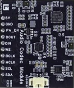
 Design with Audio Codec Module in Cirkit Designer
Introduction
The LAFVIN ACM Audio Codec Module is a versatile device designed to encode and decode digital audio signals, enabling seamless conversion between analog and digital formats. This module is essential for audio processing applications, where sound quality, compression, and efficient signal management are critical. It is widely used in devices such as audio recorders, media players, and communication systems.
Explore Projects Built with Audio Codec Module
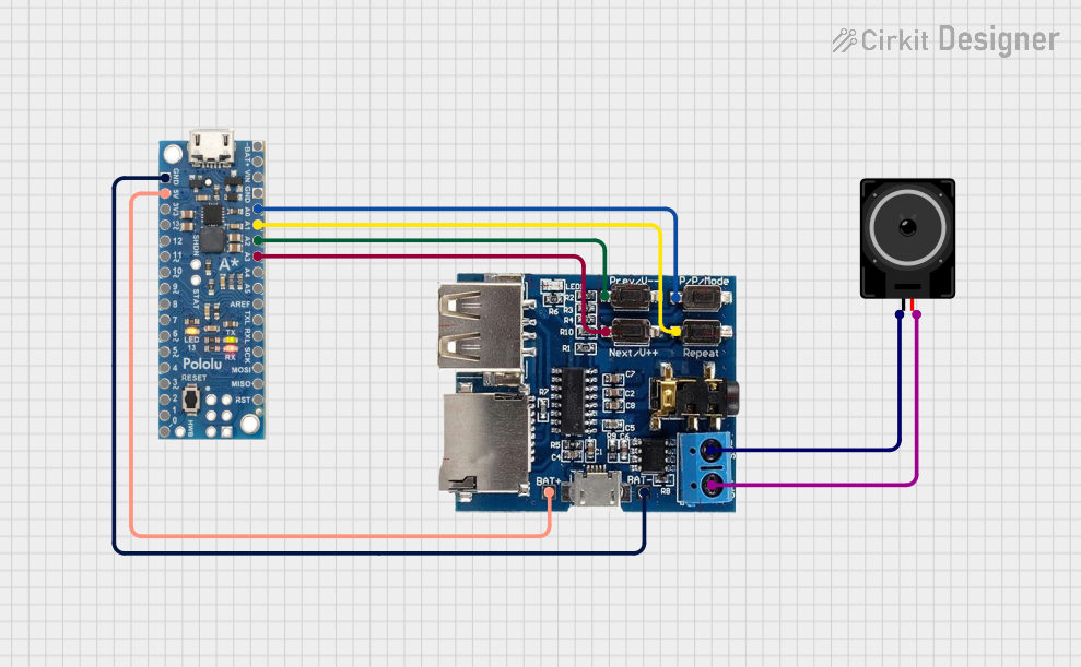 Open Project in Cirkit Designer
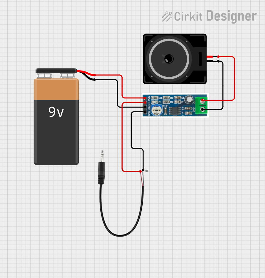 Open Project in Cirkit Designer
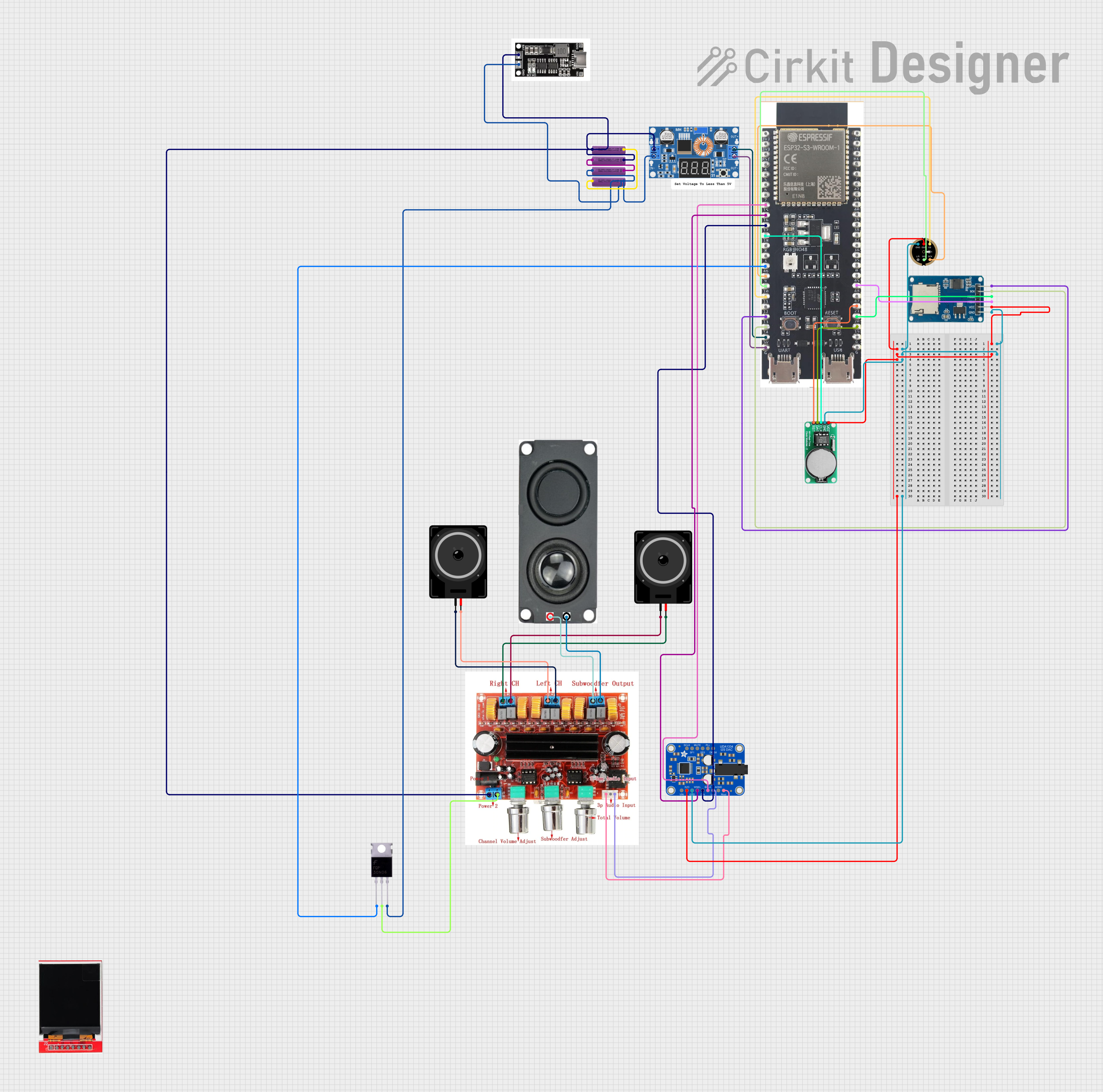 Open Project in Cirkit Designer
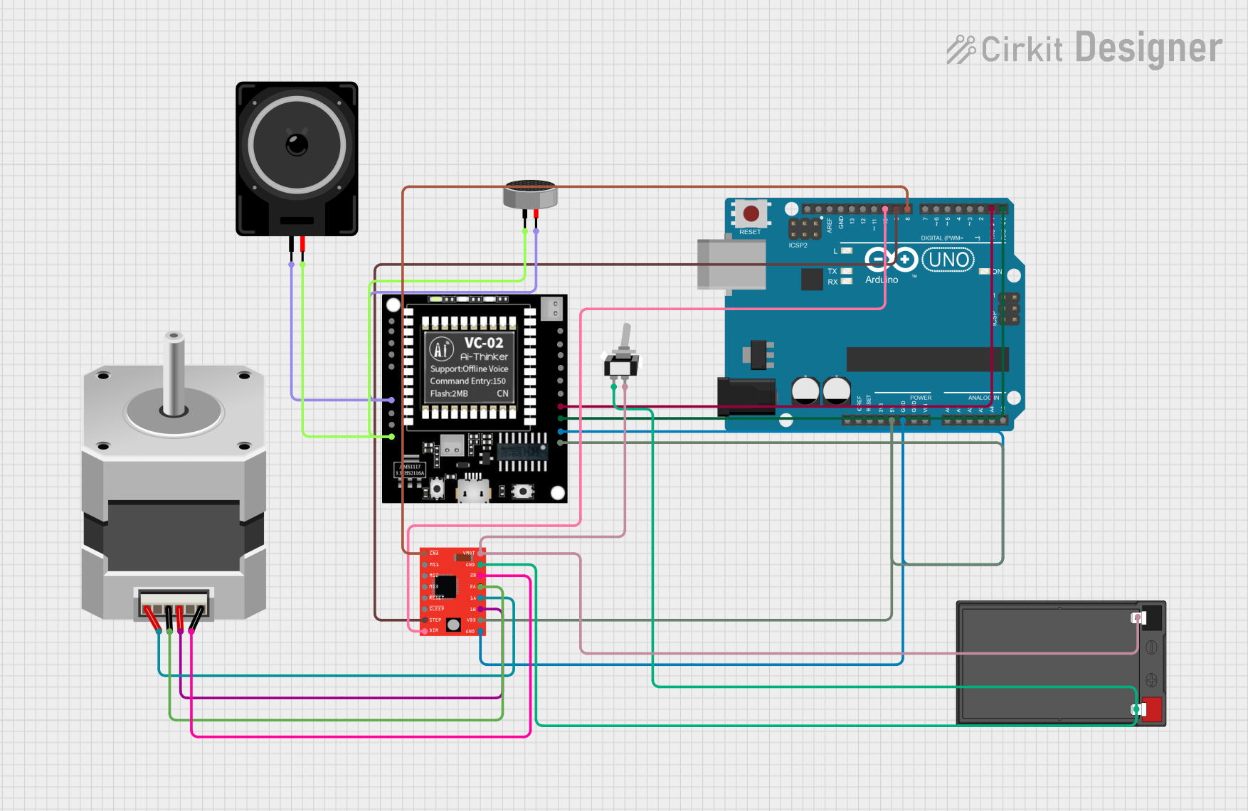 Open Project in Cirkit Designer
Explore Projects Built with Audio Codec Module
Open Project in Cirkit DesignerOpen Project in Cirkit DesignerOpen Project in Cirkit DesignerOpen Project in Cirkit DesignerCommon Applications and Use Cases
- Audio recording and playback systems
- Digital signal processing (DSP) applications
- Voice communication devices (e.g., VoIP phones)
- Media streaming devices
- Audio mixing and editing equipment
Technical Specifications
The LAFVIN ACM Audio Codec Module is engineered to deliver high performance and reliability. Below are its key technical specifications:
| Parameter | Value |
|---|---|
| Operating Voltage | 3.3V to 5V |
| Power Consumption | < 50 mW |
| Sampling Rate | Up to 48 kHz |
| Bit Depth | 16-bit |
| Signal-to-Noise Ratio | > 90 dB |
| Communication Protocol | I2C or SPI |
| Audio Channels | Stereo (2 channels) |
| Input Impedance | 10 kΩ |
| Output Impedance | 32 Ω |
| Operating Temperature | -40°C to 85°C |
Pin Configuration and Descriptions
The LAFVIN ACM module features a standard pinout for easy integration into various systems. Below is the pin configuration:
| Pin | Name | Description |
|---|---|---|
| 1 | VCC | Power supply input (3.3V to 5V). |
| 2 | GND | Ground connection. |
| 3 | SCL | Serial Clock Line for I2C communication. |
| 4 | SDA | Serial Data Line for I2C communication. |
| 5 | MISO | Master In Slave Out for SPI communication. |
| 6 | MOSI | Master Out Slave In for SPI communication. |
| 7 | SCK | Serial Clock for SPI communication. |
| 8 | LRCK | Left/Right Clock for audio channel synchronization. |
| 9 | BCLK | Bit Clock for audio data transfer. |
| 10 | DIN | Digital audio input. |
| 11 | DOUT | Digital audio output. |
| 12 | RESET | Reset pin to initialize the module. |
Usage Instructions
How to Use the Component in a Circuit
- Power the Module: Connect the VCC pin to a 3.3V or 5V power source and the GND pin to ground.
- Choose Communication Protocol: Decide whether to use I2C or SPI for communication. Connect the appropriate pins (SCL/SDA for I2C or MISO/MOSI/SCK for SPI) to your microcontroller.
- Audio Signal Connections:
- Connect the analog audio input to the DIN pin.
- Connect the analog audio output to the DOUT pin.
- Clock Signals: Ensure proper synchronization by connecting the LRCK and BCLK pins to the corresponding clock signals from your microcontroller or DSP.
- Reset the Module: Use the RESET pin to initialize the module during startup.
Important Considerations and Best Practices
- Power Supply: Ensure a stable power supply to avoid noise or distortion in audio signals.
- Clock Configuration: Properly configure the LRCK and BCLK signals to match the desired sampling rate and bit depth.
- Impedance Matching: Match the input and output impedances to avoid signal loss or degradation.
- Decoupling Capacitors: Place decoupling capacitors near the VCC pin to filter out power supply noise.
- Avoid Overloading: Do not exceed the maximum input/output voltage levels to prevent damage to the module.
Example: Connecting to an Arduino UNO
Below is an example of how to connect and program the LAFVIN ACM module with an Arduino UNO using the I2C protocol:
Wiring Diagram
| LAFVIN ACM Pin | Arduino UNO Pin |
|---|---|
| VCC | 5V |
| GND | GND |
| SCL | A5 (SCL) |
| SDA | A4 (SDA) |
| RESET | Digital Pin 7 |
Arduino Code Example
#include <Wire.h>

// I2C address of the LAFVIN ACM module
#define AUDIO_CODEC_ADDR 0x1A

void setup() {
  Wire.begin(); // Initialize I2C communication
  pinMode(7, OUTPUT); // Set RESET pin as output
  digitalWrite(7, HIGH); // Deactivate RESET (active low)

  Serial.begin(9600); // Start serial communication for debugging
  Serial.println("Initializing Audio Codec Module...");

  // Example: Configure the module (pseudo-configuration)
  Wire.beginTransmission(AUDIO_CODEC_ADDR);
  Wire.write(0x00); // Register address
  Wire.write(0x01); // Example configuration value
  Wire.endTransmission();

  Serial.println("Audio Codec Module initialized.");
}

void loop() {
  // Add your audio processing code here
}
Troubleshooting and FAQs
Common Issues and Solutions
No Audio Output:
- Verify that the power supply voltage is within the specified range.
- Check the connections to the DIN and DOUT pins.
- Ensure the LRCK and BCLK signals are properly configured.
Distorted Audio:
- Confirm that the sampling rate and bit depth match the audio source.
- Use decoupling capacitors to reduce power supply noise.
- Check for impedance mismatches in the circuit.
Communication Failure:
- Ensure the correct I2C or SPI pins are connected.
- Verify the I2C address or SPI configuration in your code.
- Check for loose or faulty connections.
FAQs
Q1: Can the module operate at 5V?
Yes, the LAFVIN ACM module supports an operating voltage range of 3.3V to 5V.
Q2: What is the maximum sampling rate supported?
The module supports a maximum sampling rate of 48 kHz.
Q3: Can I use this module with a Raspberry Pi?
Yes, the module can be interfaced with a Raspberry Pi using I2C or SPI communication.
Q4: How do I reset the module?
Pull the RESET pin low momentarily and then set it high to reset the module.
Q5: Is the module compatible with mono audio?
Yes, the module can process mono audio by using only one channel.
This concludes the documentation for the LAFVIN ACM Audio Codec Module. For further assistance, refer to the manufacturer's datasheet or contact technical support.