How to Use D-Pad: Examples, Pinouts, and Specs
Introduction
The D-Pad, or Directional Pad, is a directional control interface commonly found on game controllers. It consists of four or more buttons arranged in a cross shape, enabling users to navigate menus or control movement in games. The D-Pad is widely used in gaming consoles, handheld devices, and custom electronics projects requiring directional input.
Explore Projects Built with D-Pad
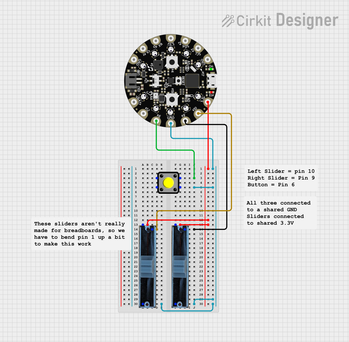

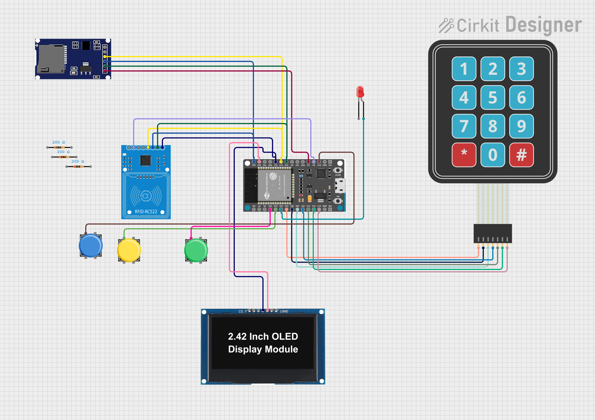

Explore Projects Built with D-Pad
Common Applications and Use Cases
- Game controllers for consoles and PCs
- Navigation in user interfaces (e.g., menu selection)
- Robotics and remote control systems
- Custom DIY electronics projects for directional input
Technical Specifications
Key Technical Details
- Input Type: Digital (on/off for each direction)
- Number of Buttons: Typically 4 (Up, Down, Left, Right), with optional diagonals
- Voltage Range: 3.3V to 5V (compatible with most microcontrollers)
- Current Consumption: Minimal (depends on pull-up or pull-down resistors)
- Interface: Individual button outputs or matrix configuration
- Debouncing: May require external or software-based debouncing
Pin Configuration and Descriptions
The D-Pad typically has 5 pins: one common ground and four directional outputs. Below is a table describing the pin configuration:
| Pin | Name | Description |
|---|---|---|
| 1 | Common Ground | Shared ground connection for all buttons. |
| 2 | Up | Output pin for the "Up" button. Connects to ground when pressed. |
| 3 | Down | Output pin for the "Down" button. Connects to ground when pressed. |
| 4 | Left | Output pin for the "Left" button. Connects to ground when pressed. |
| 5 | Right | Output pin for the "Right" button. Connects to ground when pressed. |
Note: Some D-Pads may use a matrix configuration, where multiple buttons share rows and columns. In such cases, additional decoding logic is required.
Usage Instructions
How to Use the D-Pad in a Circuit
Connect the Pins:
- Connect the "Common Ground" pin to the ground (GND) of your circuit.
- Connect each directional pin (Up, Down, Left, Right) to a digital input pin on your microcontroller.
- Use pull-up or pull-down resistors to ensure stable signals when buttons are not pressed.
Read Button States:
- When a button is pressed, its corresponding pin will be pulled to ground.
- Use digital input pins on your microcontroller to detect the button press.
Debouncing:
- Mechanical buttons can produce noise or "bouncing" when pressed or released.
- Implement software-based debouncing or use external capacitors to filter out noise.
Example: Connecting a D-Pad to an Arduino UNO
Below is an example of how to connect and read a D-Pad using an Arduino UNO:
Circuit Connections
- Connect the "Common Ground" pin of the D-Pad to the GND pin on the Arduino.
- Connect the "Up", "Down", "Left", and "Right" pins to Arduino digital pins 2, 3, 4, and 5, respectively.
- Use internal pull-up resistors in the Arduino code to simplify the circuit.
Arduino Code
// Define pin connections for the D-Pad
const int upPin = 2;
const int downPin = 3;
const int leftPin = 4;
const int rightPin = 5;

void setup() {
  // Initialize serial communication for debugging
  Serial.begin(9600);

  // Set D-Pad pins as inputs with internal pull-up resistors
  pinMode(upPin, INPUT_PULLUP);
  pinMode(downPin, INPUT_PULLUP);
  pinMode(leftPin, INPUT_PULLUP);
  pinMode(rightPin, INPUT_PULLUP);
}

void loop() {
  // Read the state of each button (LOW means pressed)
  bool upPressed = digitalRead(upPin) == LOW;
  bool downPressed = digitalRead(downPin) == LOW;
  bool leftPressed = digitalRead(leftPin) == LOW;
  bool rightPressed = digitalRead(rightPin) == LOW;

  // Print the button states to the Serial Monitor
  if (upPressed) {
    Serial.println("Up button pressed");
  }
  if (downPressed) {
    Serial.println("Down button pressed");
  }
  if (leftPressed) {
    Serial.println("Left button pressed");
  }
  if (rightPressed) {
    Serial.println("Right button pressed");
  }

  // Add a small delay to avoid flooding the Serial Monitor
  delay(100);
}
Important Considerations and Best Practices
- Debouncing: Always account for button bounce to avoid false triggers.
- Voltage Compatibility: Ensure the D-Pad operates within the voltage range of your microcontroller.
- Pull-Up Resistors: Use internal or external pull-up resistors to stabilize the signal.
- Durability: D-Pads are mechanical components and may wear out over time with heavy use.
Troubleshooting and FAQs
Common Issues and Solutions
| Issue | Possible Cause | Solution |
|---|---|---|
| Button presses are not detected | Loose or incorrect wiring | Verify all connections and ensure proper grounding. |
| Multiple buttons register simultaneously | Button bounce or matrix misconfiguration | Implement software debouncing or check matrix wiring. |
| Button state is unstable | Missing pull-up or pull-down resistors | Use internal pull-up resistors or add external resistors to stabilize inputs. |
| No response from the D-Pad | Voltage mismatch or damaged component | Ensure voltage compatibility and check for physical damage. |
FAQs
Can I use the D-Pad with a 3.3V microcontroller?
- Yes, most D-Pads are compatible with 3.3V and 5V systems. Verify the specifications of your specific D-Pad.
Do I need external resistors for the D-Pad?
- If your microcontroller supports internal pull-up resistors, external resistors are not necessary. Otherwise, use 10kΩ pull-up resistors.
How do I add diagonal inputs?
- Diagonal inputs can be detected by checking for simultaneous presses of two adjacent buttons (e.g., Up + Right for "Up-Right").
Can I use the D-Pad for analog input?
- No, the D-Pad is a digital input device. For analog input, consider using a joystick.
By following this documentation, you can effectively integrate a D-Pad into your projects for reliable directional input.