How to Use lm324: Examples, Pinouts, and Specs
Introduction
The LM324 is a versatile and widely used integrated circuit that consists of four independent, high-gain, internally frequency-compensated operational amplifiers (op-amps) designed to operate from a single power supply over a wide range of voltages. It is manufactured by various semiconductor companies, with the part ID "IC" often being a generic designation.
Explore Projects Built with lm324
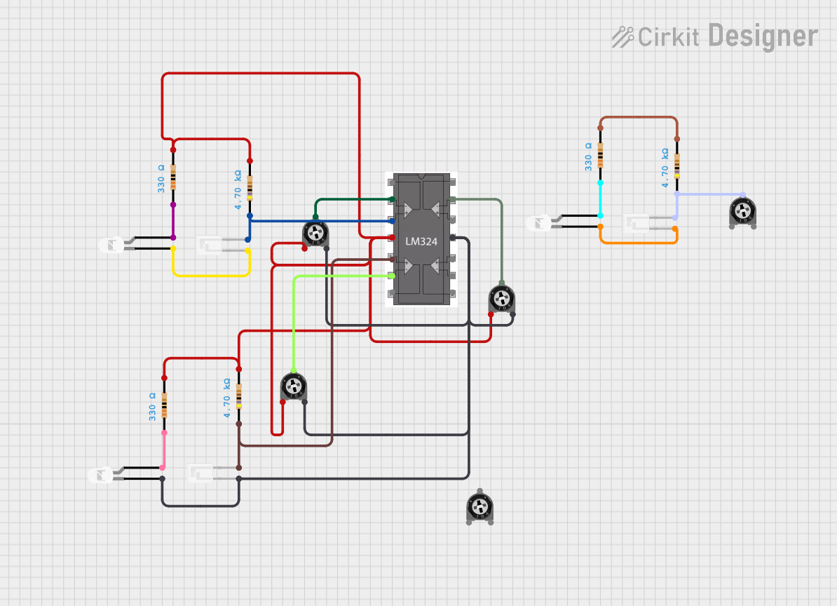
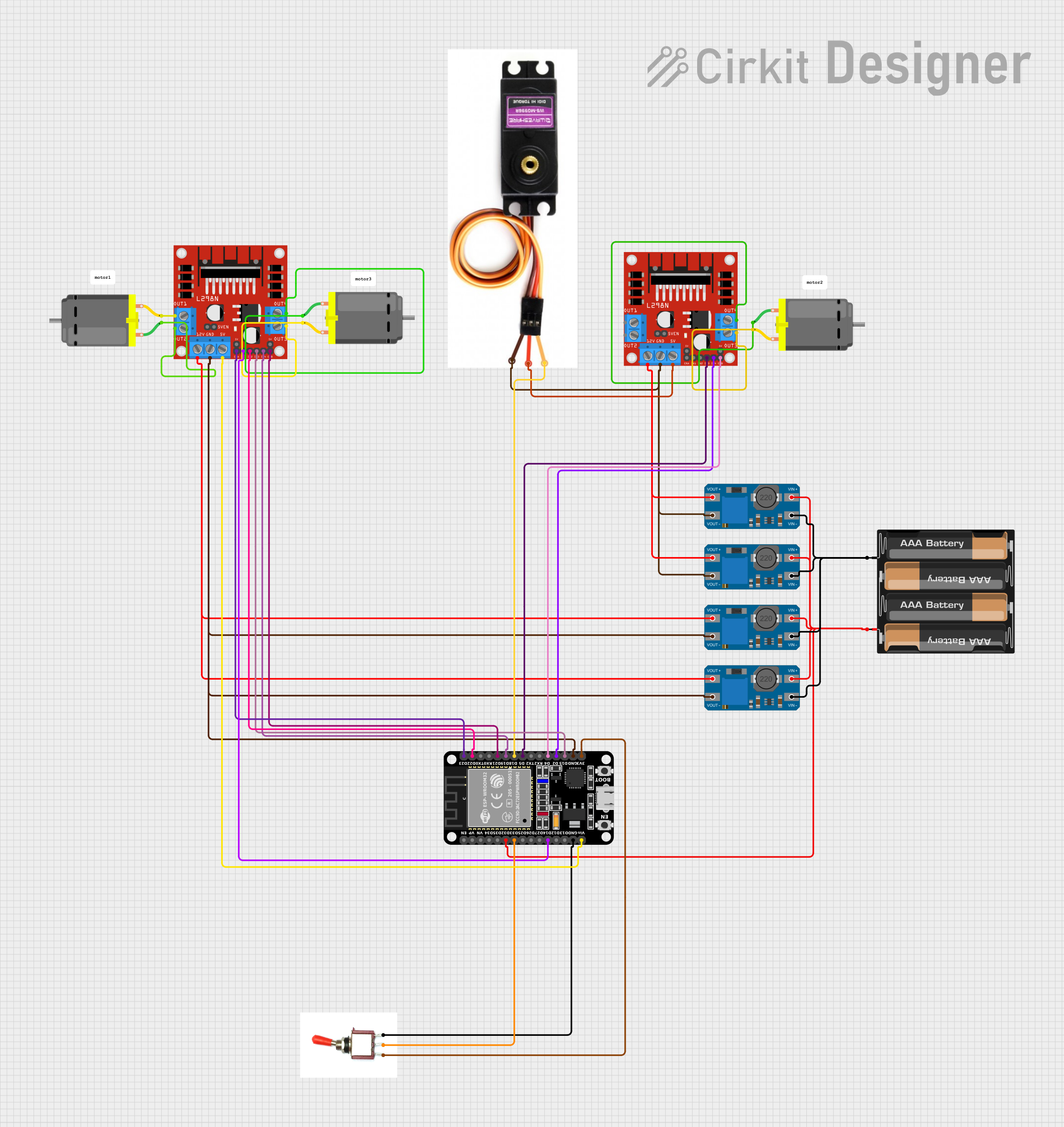
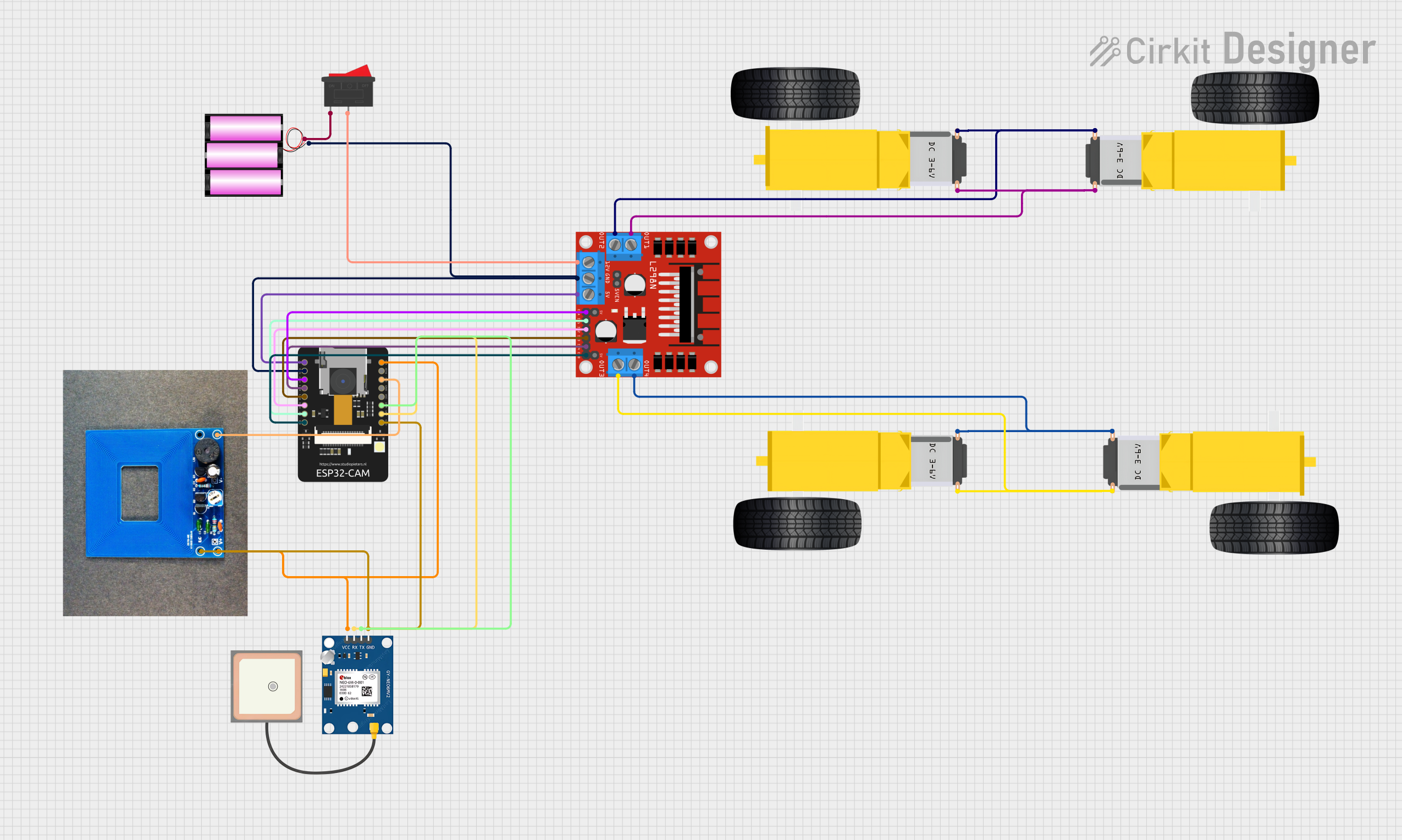
Explore Projects Built with lm324
Common Applications and Use Cases
- Audio processing circuits
- Signal amplifiers
- Active filters
- Voltage followers and comparators
- Oscillators
- Battery chargers
- Sensor interfaces
Technical Specifications
Key Technical Details
- Power Supply Voltage Range: 3V to 32V (single supply) or ±1.5V to ±16V (dual supply)
- Input Offset Voltage: 2mV (typical)
- Input Bias Current: 20nA (typical)
- Large Output Voltage Swing: 0V to V+ - 1.5V
- Common Mode Rejection Ratio (CMRR): 70dB (typical)
- Supply Current (per amplifier): 0.7mA (typical)
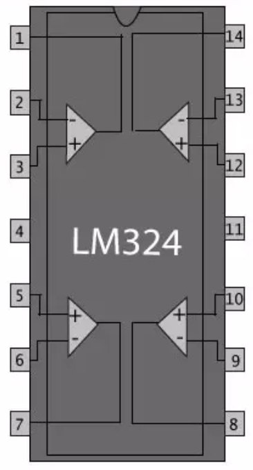
Pin Configuration and Descriptions
| Pin Number | Pin Name | Description |
|---|---|---|
| 1 | Output 1 | Output of Amplifier 1 |
| 2 | Inverting Input 1 | Inverting input of Amplifier 1 |
| 3 | Non-Inverting Input 1 | Non-inverting input of Amplifier 1 |
| 4 | GND/V- | Ground or negative supply voltage |
| 5 | Non-Inverting Input 2 | Non-inverting input of Amplifier 2 |
| 6 | Inverting Input 2 | Inverting input of Amplifier 2 |
| 7 | Output 2 | Output of Amplifier 2 |
| 8 | V+ | Positive supply voltage |
| 9 | Output 3 | Output of Amplifier 3 |
| 10 | Inverting Input 3 | Inverting input of Amplifier 3 |
| 11 | Non-Inverting Input 3 | Non-inverting input of Amplifier 3 |
| 12 | GND/V- | Ground or negative supply voltage (same as pin 4) |
| 13 | Non-Inverting Input 4 | Non-inverting input of Amplifier 4 |
| 14 | Inverting Input 4 | Inverting input of Amplifier 4 |
| 15 | Output 4 | Output of Amplifier 4 |
Usage Instructions
How to Use the LM324 in a Circuit
Power Supply Connections:
- Connect the positive supply voltage to pin 8 (V+).
- Connect the ground or negative supply voltage to pin 4 (GND/V-).
Signal Input:
- Apply the input signal to the non-inverting input (pins 3, 5, 11, 13) for a non-inverted output.
- Use the inverting input (pins 2, 6, 10, 14) for signal inversion.
Output:
- Connect the output (pins 1, 7, 9, 15) to the next stage of your circuit or to a load, ensuring it does not exceed the current rating.
Feedback and Gain Control:
- Use feedback resistors between the output and inverting input to set the gain of the amplifier.
Important Considerations and Best Practices
- Bypass capacitors (typically 0.1µF) should be placed close to the power supply pins to filter out noise.
- Avoid exceeding the maximum supply voltage to prevent damage to the op-amp.
- Ensure that the differential input voltage and the input voltage range are within specified limits.
- Keep the output load within the current driving capability of the op-amp to avoid overheating and damage.
Troubleshooting and FAQs
Common Issues Users Might Face
Output Not as Expected:
- Check if the power supply is connected correctly and is within the specified range.
- Verify the input signals and feedback network for proper operation.
Op-Amp Overheating:
- Ensure the output load does not exceed the current rating of the op-amp.
- Check for short circuits or incorrect wiring in the circuit.
Noise in the Output Signal:
- Use bypass capacitors to minimize power supply noise.
- Keep signal wires away from high-current paths to reduce interference.
Solutions and Tips for Troubleshooting
- Double-check all connections against the circuit diagram.
- Measure voltages at the power supply pins and inputs to ensure they are within the specified range.
- Use an oscilloscope to check for proper signal waveforms at the output.
FAQs
Q: Can the LM324 be used with a dual power supply? A: Yes, the LM324 can operate with a dual power supply ranging from ±1.5V to ±16V.
Q: What is the maximum output current of the LM324? A: The maximum output current is not explicitly specified, but it is typically around 20-40mA. Always refer to the manufacturer's datasheet for exact specifications.
Q: Can I use the LM324 for high-frequency applications? A: The LM324 is not designed for high-frequency applications due to its limited bandwidth. It is more suitable for low to moderate frequency applications.
Q: Is there a recommended layout for the LM324 in PCB design? A: Yes, it is recommended to place bypass capacitors close to the power supply pins and to keep the feedback paths as short as possible to reduce noise and oscillations.
Q: Can I replace the LM324 with another op-amp in my circuit? A: It depends on the specifications of the other op-amp. Ensure that the replacement has similar or better characteristics and is compatible with the power supply and signal levels of your circuit.
Example Connection to an Arduino UNO
The LM324 can be used with an Arduino UNO for various analog signal processing tasks. Below is an example code snippet for reading an analog signal processed by the LM324.
// Define the analog pin connected to the LM324 output
const int analogPin = A0;

void setup() {
  // Initialize serial communication at 9600 baud rate
  Serial.begin(9600);
}

void loop() {
  // Read the analog value from the LM324 output
  int sensorValue = analogRead(analogPin);

  // Convert the analog reading (which goes from 0 - 1023) to a voltage (0 - 5V)
  float voltage = sensorValue * (5.0 / 1023.0);

  // Print out the voltage
  Serial.println(voltage);

  // Wait for a bit to avoid spamming the serial output
  delay(500);
}
Remember to consult the datasheet of the specific LM324 variant you are using for precise specifications and application notes.