How to Use Solid State Relay x2: Examples, Pinouts, and Specs
Introduction
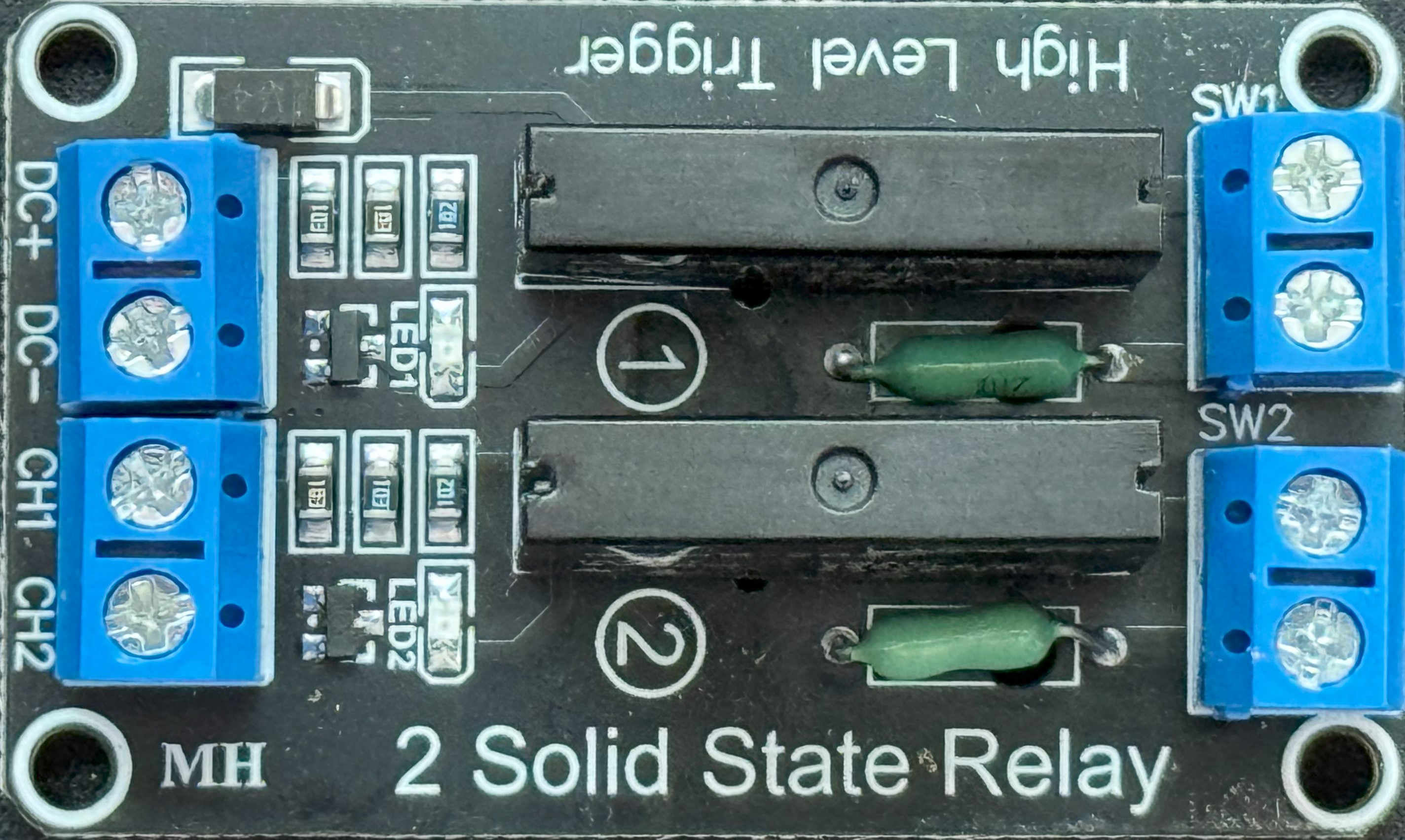
A Solid State Relay (SSR) is an electronic switching device that uses semiconductor components, such as thyristors, triacs, or transistors, to perform switching operations. Unlike mechanical relays, SSRs have no moving parts, which allows for faster switching speeds, silent operation, and a significantly longer lifespan. The "x2" designation typically refers to a dual-channel SSR module, capable of controlling two independent loads.
Explore Projects Built with Solid State Relay x2


Explore Projects Built with Solid State Relay x2
Common Applications and Use Cases
- Industrial automation systems
- Home automation (e.g., controlling lights, fans, or heaters)
- Motor control and speed regulation
- Temperature control systems (e.g., ovens, HVAC systems)
- High-frequency switching applications
- Isolation between low-voltage control circuits and high-voltage loads
Technical Specifications
Key Technical Details
- Input Voltage (Control Signal): 3–32V DC
- Output Voltage (Load): 24–380V AC
- Output Current (Load): Up to 2A per channel
- Trigger Current: 7.5mA (typical)
- Switching Speed: <10ms
- Dielectric Strength: 2500V AC (isolation between input and output)
- Operating Temperature Range: -30°C to 80°C
- Channels: 2 (dual-channel module)
Pin Configuration and Descriptions
The Solid State Relay x2 module typically has the following pin layout:
Input Side (Control Signal)
| Pin Name | Description |
|---|---|
| IN1 | Control signal input for Channel 1 |
| IN2 | Control signal input for Channel 2 |
| GND | Ground for the control signal |
| VCC | Positive voltage for the control signal (3–32V DC) |
Output Side (Load)
| Pin Name | Description |
|---|---|
| OUT1+ | AC load terminal for Channel 1 (Live) |
| OUT1- | AC load terminal for Channel 1 (Neutral) |
| OUT2+ | AC load terminal for Channel 2 (Live) |
| OUT2- | AC load terminal for Channel 2 (Neutral) |
Usage Instructions
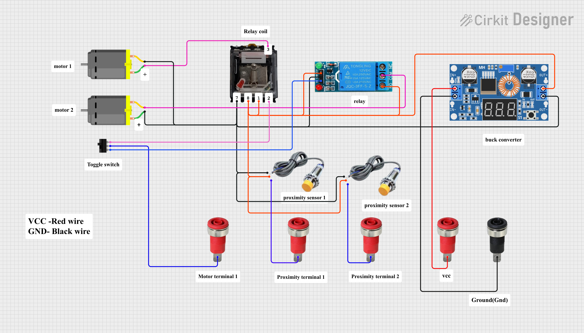
How to Use the Component in a Circuit
Power the Control Side:
- Connect the VCC pin to a DC voltage source (3–32V DC).
- Connect the GND pin to the ground of the control circuit.
Connect the Control Signals:
- Use a microcontroller (e.g., Arduino UNO) or other control device to send signals to the IN1 and IN2 pins.
- A HIGH signal (typically 5V) will activate the corresponding relay channel.
Connect the Load:
- Connect the AC load to the OUT1+ and OUT1- terminals for Channel 1, and OUT2+ and OUT2- for Channel 2.
- Ensure the load voltage and current do not exceed the SSR's rated limits (24–380V AC, 2A per channel).
Isolation:
- The SSR provides electrical isolation between the control and load sides. Ensure proper grounding to avoid noise or interference.
Important Considerations and Best Practices
- Heat Dissipation: SSRs generate heat during operation. Use a heat sink or ensure proper ventilation to prevent overheating.
- Load Type: SSRs are best suited for resistive loads (e.g., heaters, incandescent bulbs). For inductive loads (e.g., motors), use an SSR with zero-crossing detection or a snubber circuit.
- Voltage Spikes: Protect the SSR from voltage spikes using appropriate surge protection devices.
- Testing: Always test the SSR with a low-power load before connecting high-power equipment.
Example: Connecting to an Arduino UNO
Below is an example of how to control the Solid State Relay x2 module using an Arduino UNO:
// Define the control pins for the SSR module
const int ssrChannel1 = 7; // Pin connected to IN1
const int ssrChannel2 = 8; // Pin connected to IN2

void setup() {
  // Set the SSR control pins as outputs
  pinMode(ssrChannel1, OUTPUT);
  pinMode(ssrChannel2, OUTPUT);

  // Initialize both channels to OFF
  digitalWrite(ssrChannel1, LOW);
  digitalWrite(ssrChannel2, LOW);
}

void loop() {
  // Turn ON Channel 1 for 5 seconds
  digitalWrite(ssrChannel1, HIGH);
  delay(5000);

  // Turn OFF Channel 1
  digitalWrite(ssrChannel1, LOW);
  delay(1000);

  // Turn ON Channel 2 for 3 seconds
  digitalWrite(ssrChannel2, HIGH);
  delay(3000);

  // Turn OFF Channel 2
  digitalWrite(ssrChannel2, LOW);
  delay(1000);
}
Troubleshooting and FAQs
Common Issues and Solutions
SSR Not Switching the Load:
- Cause: Insufficient control signal voltage or current.
- Solution: Ensure the control signal voltage is within the specified range (3–32V DC) and the current is at least 7.5mA.
Overheating:
- Cause: Excessive load current or poor ventilation.
- Solution: Verify the load current does not exceed 2A per channel. Use a heat sink or improve airflow around the SSR.
Load Flickering or Unstable Operation:
- Cause: Noise or interference in the control signal.
- Solution: Use decoupling capacitors on the control side and ensure proper grounding.
No Isolation Between Control and Load:
- Cause: Incorrect wiring or damaged SSR.
- Solution: Double-check the wiring and test the SSR with a multimeter to confirm isolation.
FAQs
Can I use the SSR with DC loads?
- No, this SSR is designed for AC loads only. For DC loads, use a DC-specific SSR.
What happens if I exceed the rated current?
- Exceeding the rated current can damage the SSR permanently. Always ensure the load current is within the specified limits.
Can I control both channels independently?
- Yes, each channel has its own control input (IN1 and IN2) and operates independently.
Is the SSR polarity-sensitive on the load side?
- No, the load side terminals (OUT1+/OUT1-, OUT2+/OUT2-) are not polarity-sensitive for AC loads.