How to Use Arcade Button (blue): Examples, Pinouts, and Specs
Introduction
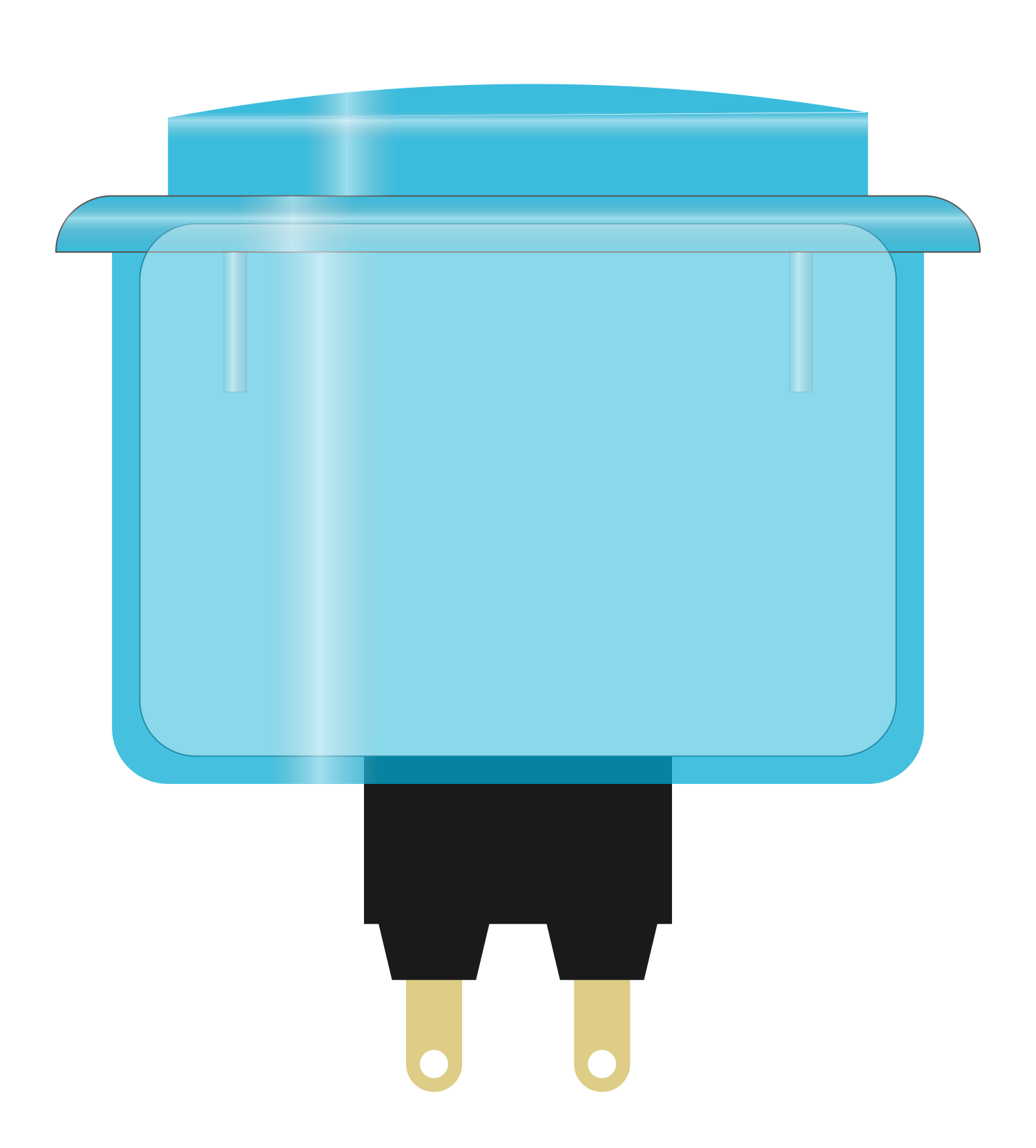
The Arcade Button (blue) is a large, durable push button switch designed for high-traffic use in arcade games and interactive projects. Its sizeable actuator surface allows for easy activation, making it ideal for applications where quick and responsive input is necessary. Commonly used in DIY arcade cabinets, educational projects, and interactive installations, the arcade button provides a tactile and visual response that is satisfying for users.
Explore Projects Built with Arcade Button (blue)
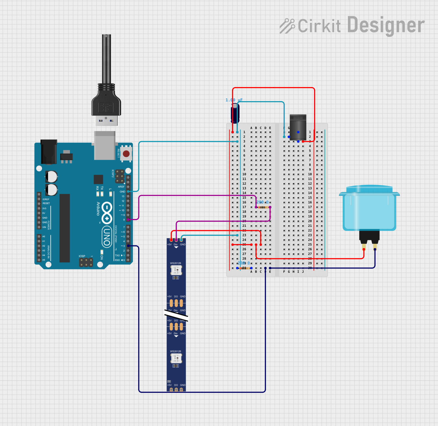
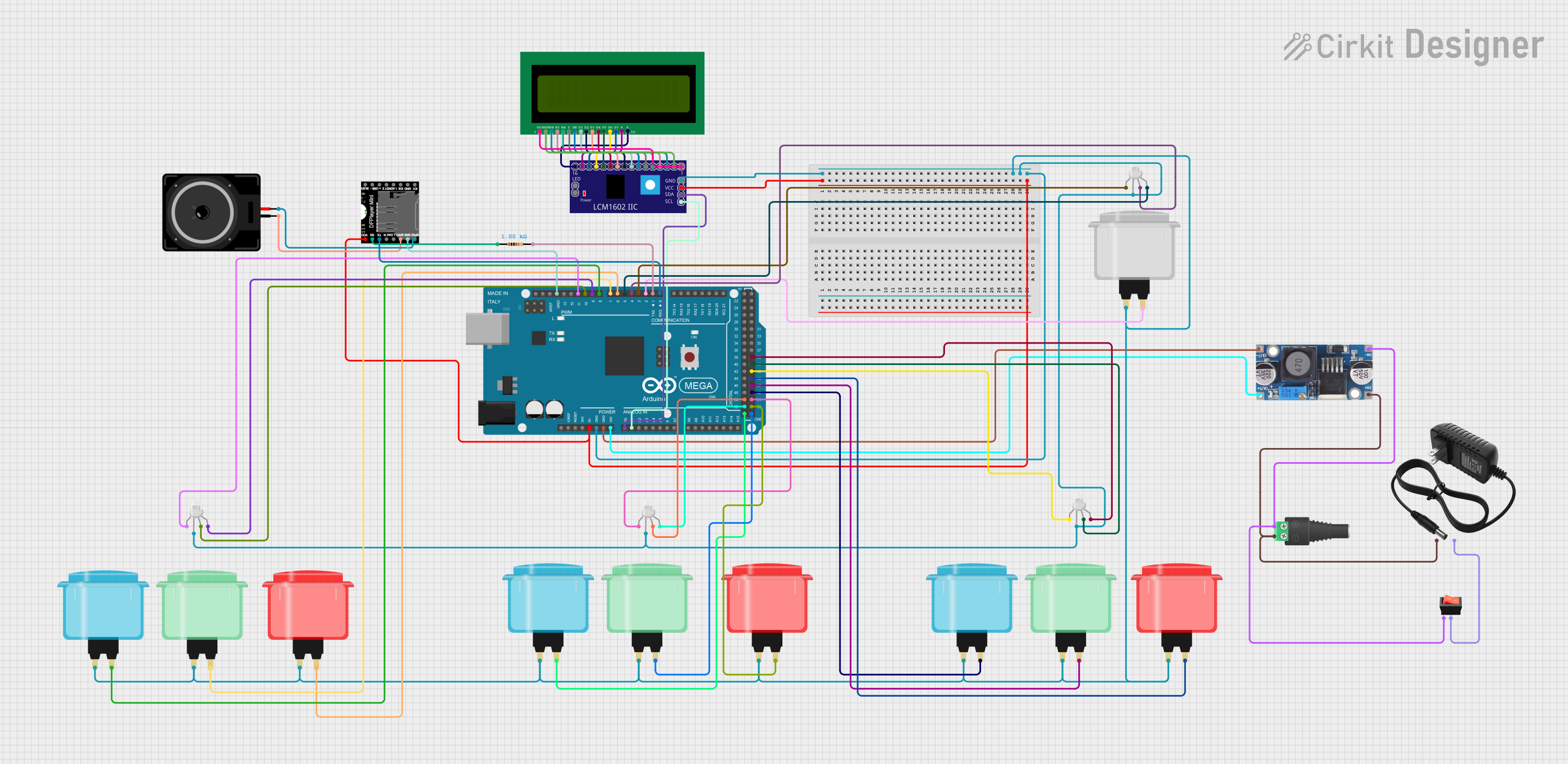
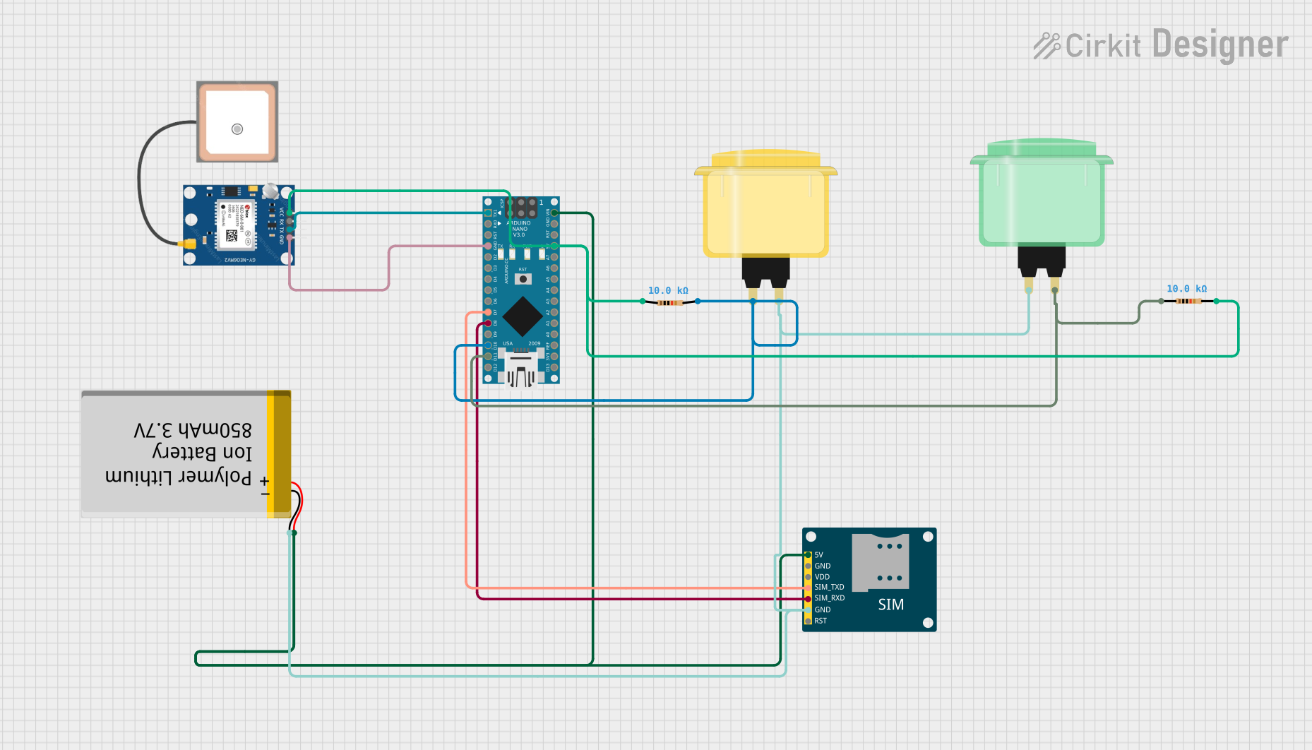
Explore Projects Built with Arcade Button (blue)
Technical Specifications
Key Technical Details
- Switch Type: Momentary push button
- Color: Blue
- Material: Durable plastic (actuator) and microswitch
- Contact Type: Normally open (NO)
- Voltage Rating: Typically 12V (check specific model for maximum voltage)
- Current Rating: 10A at 125VAC, 5A at 250VAC (check specific model for exact ratings)
- Contact Resistance: 50 mΩ max
- Insulation Resistance: 100 MΩ min at 500VDC
- Dielectric Strength: 1,000VAC for 1 minute
- Operating Force: Approximately 3N to 5N
- Life Expectancy: 1,000,000 cycles minimum
Pin Configuration and Descriptions
| Pin Number | Description |
|---|---|
| 1 | Common (COM) |
| 2 | Normally Open (NO) |
| 3 | Normally Closed (NC) |
Note: The pin configuration may vary slightly depending on the manufacturer. Always check the datasheet for your specific model.
Usage Instructions
Incorporating the Arcade Button into a Circuit
- Identify the Pins: Locate the COM, NO, and NC pins on the microswitch attached to the arcade button.
- Wiring: Connect the COM pin to one side of your power supply. The NO pin should be connected to the input pin on your microcontroller or to the circuit you wish to control.
- Mounting: Secure the button in place using the threaded barrel and included nut. Ensure it is tight enough to prevent movement during use.
- Testing: Press the button to ensure it actuates correctly and that the circuit responds as expected.
Best Practices
- Use a pull-up or pull-down resistor on the input pin to ensure a stable signal.
- Avoid exceeding the voltage and current ratings to prevent damage to the button and your circuit.
- Regularly check the button for wear and tear, especially in high-use applications.
Example Code for Arduino UNO
// Define the pin where the arcade button is connected
const int buttonPin = 2;

// Variable for reading the button status
int buttonState = 0;

void setup() {
  // Initialize the button pin as an input
  pinMode(buttonPin, INPUT_PULLUP);
  // Initialize serial communication at 9600 bits per second
  Serial.begin(9600);
}

void loop() {
  // Read the state of the button value
  buttonState = digitalRead(buttonPin);

  // Check if the button is pressed
  if (buttonState == LOW) {
    // If the button is pressed, print this message
    Serial.println("Button Pressed");
    // Delay a little bit to avoid bouncing
    delay(100);
  }
}
Note: The INPUT_PULLUP mode enables the internal pull-up resistor, negating the need for an external resistor.
Troubleshooting and FAQs
Common Issues
- Button Not Responding: Ensure all connections are secure and the button is properly mounted. Check for any signs of physical damage.
- Intermittent Button Response: This could be due to switch bounce. Implement a debounce algorithm in your code or use a hardware debounce circuit.
- Excessive Wear: If the button is used extensively, the contacts may wear out. Replace the button if it exceeds its life expectancy.
FAQs
Q: Can I use the arcade button with a higher voltage than 12V? A: It is not recommended to exceed the voltage rating specified by the manufacturer. Doing so may damage the button and pose a safety risk.
Q: How do I know if the button is wired correctly? A: Use a multimeter to check for continuity between the COM and NO pins when the button is pressed. If there is continuity, the button is wired correctly.
Q: Can I use the arcade button with a microcontroller that operates at 3.3V? A: Yes, the arcade button is a mechanical switch and can be used with any microcontroller regardless of its operating voltage. Ensure that the input pin is configured with the appropriate pull-up or pull-down resistor.
Q: What is the purpose of the NC pin? A: The Normally Closed (NC) pin is connected to COM when the button is not pressed. It can be used in circuits where you want the default state to be ON and pressing the button breaks the circuit.
For further assistance, consult the manufacturer's datasheet or contact technical support.