How to Use PLUTOPLUS: Examples, Pinouts, and Specs
Introduction
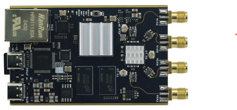
PLUTOPLUS is a programmable logic device (PLD) designed to enable the implementation of custom logic functions and circuits. It provides a flexible and efficient solution for creating digital systems without the need for fixed hardware configurations. PLUTOPLUS is widely used in applications such as signal processing, control systems, data manipulation, and prototyping of digital designs. Its reprogrammable nature makes it an ideal choice for iterative development and testing.
Common applications of PLUTOPLUS include:
- Digital signal processing (DSP)
- Embedded control systems
- Data routing and manipulation
- Prototyping custom digital circuits
- Hardware acceleration for computational tasks
Explore Projects Built with PLUTOPLUS


Explore Projects Built with PLUTOPLUS
Technical Specifications
Below are the key technical details and pin configuration for the PLUTOPLUS device:
Key Technical Details
- Logic Elements (LEs): 10,000
- Operating Voltage: 3.3V ± 10%
- Maximum Clock Frequency: 200 MHz
- I/O Pins: 64 configurable pins
- Power Consumption: 1.5W (typical)
- Programming Interface: JTAG
- Configuration Memory: SRAM-based (volatile)
- Package Type: TQFP-100 (Thin Quad Flat Package, 100 pins)
- Temperature Range: -40°C to +85°C (industrial grade)
Pin Configuration and Descriptions
The PLUTOPLUS device features 100 pins, with 64 configurable I/O pins. Below is a summary of the key pin functions:
| Pin Name | Type | Description |
|---|---|---|
| VCC | Power | 3.3V power supply input. |
| GND | Ground | Ground connection. |
| CLK_IN | Input | Clock input for the internal logic. |
| RESET | Input | Active-low reset pin to initialize the device. |
| JTAG_TDI | Input | JTAG Test Data Input for programming and debugging. |
| JTAG_TDO | Output | JTAG Test Data Output for programming and debugging. |
| JTAG_TCK | Input | JTAG Test Clock for synchronization during programming. |
| JTAG_TMS | Input | JTAG Test Mode Select for programming and debugging. |
| IO[0-63] | Configurable I/O | General-purpose input/output pins for custom logic functions. |
| VREF | Input | Reference voltage for I/O pins (optional, for differential signaling). |
| NC | Not Connected | Pins with no internal connection (leave unconnected in the circuit). |
Usage Instructions
How to Use the PLUTOPLUS in a Circuit
- Power Supply: Connect the VCC pin to a stable 3.3V power source and the GND pin to ground.
- Clock Input: Provide a clock signal to the CLK_IN pin. Ensure the clock frequency does not exceed 200 MHz.
- Programming: Use a JTAG programmer to upload your custom logic design to the PLUTOPLUS. Connect the JTAG_TDI, JTAG_TDO, JTAG_TCK, and JTAG_TMS pins to the programmer.
- I/O Configuration: Configure the IO[0-63] pins in your design software to function as inputs, outputs, or bidirectional pins, depending on your application.
- Reset: Connect the RESET pin to a pull-up resistor (e.g., 10kΩ) to keep it inactive during normal operation. Pull it low to reset the device.
Important Considerations and Best Practices
- Power Stability: Use decoupling capacitors (e.g., 0.1µF) near the VCC and GND pins to ensure stable power delivery.
- Signal Integrity: For high-speed signals, use proper PCB layout techniques, such as controlled impedance traces and ground planes.
- Programming: Ensure the JTAG programmer is compatible with the PLUTOPLUS device and that the programming software is up to date.
- Configuration Memory: Since the PLUTOPLUS uses SRAM-based configuration memory, it will lose its configuration when powered off. Use an external non-volatile memory (e.g., EEPROM) to reload the configuration automatically on power-up.
Example: Connecting PLUTOPLUS to an Arduino UNO
The PLUTOPLUS can be interfaced with an Arduino UNO for control or data exchange. Below is an example of how to toggle an LED connected to one of the PLUTOPLUS I/O pins using the Arduino:
Arduino Code Example
// Define the PLUTOPLUS I/O pin connected to the Arduino
const int plutoPin = 7; // Arduino pin connected to PLUTOPLUS IO[0]

// Setup function runs once when the Arduino is powered on or reset
void setup() {
  pinMode(plutoPin, OUTPUT); // Set the pin as an output
}

// Loop function runs continuously
void loop() {
  digitalWrite(plutoPin, HIGH); // Set the PLUTOPLUS pin high
  delay(500); // Wait for 500 milliseconds
  digitalWrite(plutoPin, LOW); // Set the PLUTOPLUS pin low
  delay(500); // Wait for 500 milliseconds
}
Troubleshooting and FAQs
Common Issues and Solutions
Device Not Responding to Programming:
- Cause: Incorrect JTAG connections or incompatible programmer.
- Solution: Verify the JTAG connections and ensure the programmer supports PLUTOPLUS.
Configuration Lost After Power Cycle:
- Cause: SRAM-based configuration memory is volatile.
- Solution: Use an external EEPROM or flash memory to store the configuration.
High Power Consumption:
- Cause: Unused I/O pins left floating.
- Solution: Configure unused I/O pins as inputs with pull-up or pull-down resistors.
Clock Signal Issues:
- Cause: Clock frequency exceeds the maximum limit or is unstable.
- Solution: Ensure the clock signal is within the 200 MHz limit and use a stable oscillator.
FAQs
Q: Can the PLUTOPLUS be reprogrammed multiple times?
A: Yes, the PLUTOPLUS is reprogrammable and supports an unlimited number of reprogramming cycles.Q: What happens if the RESET pin is left floating?
A: The device may behave unpredictably. Always connect the RESET pin to a pull-up resistor.Q: Can I use the PLUTOPLUS for analog signal processing?
A: No, the PLUTOPLUS is designed for digital logic functions only.Q: Is there a recommended software for designing logic for PLUTOPLUS?
A: Yes, use the PLUTOPLUS Design Suite, which includes tools for logic synthesis, simulation, and programming.
This concludes the documentation for the PLUTOPLUS device. For further assistance, refer to the official datasheet or contact technical support.