
How to Use USB Plug: Examples, Pinouts, and Specs
 Design with USB Plug in Cirkit Designer
Introduction
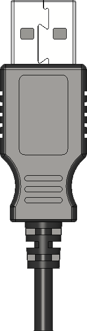
A USB plug is a standardized connector used to connect devices to a power source or to transfer data between devices. It typically features a rectangular shape with metal contacts that interface with a corresponding USB port. USB plugs are widely used in consumer electronics, including smartphones, computers, printers, and external storage devices. They are essential for charging devices, transferring files, and enabling communication between peripherals and host systems.
Explore Projects Built with USB Plug
 Open Project in Cirkit Designer
 Open Project in Cirkit Designer
 Open Project in Cirkit Designer
 Open Project in Cirkit Designer
Explore Projects Built with USB Plug
Open Project in Cirkit DesignerOpen Project in Cirkit DesignerOpen Project in Cirkit DesignerOpen Project in Cirkit DesignerCommon Applications and Use Cases
- Charging mobile devices such as smartphones, tablets, and wearables.
- Data transfer between computers and external devices like flash drives or hard drives.
- Connecting peripherals such as keyboards, mice, and printers to computers.
- Powering small electronic devices like LED lights or fans.
- Debugging and programming microcontrollers (e.g., Arduino boards).
Technical Specifications
Key Technical Details
- Connector Types: USB Type-A, USB Type-B, USB Type-C, Micro-USB, Mini-USB.
- Voltage Rating: 5V DC (standard for USB 2.0 and USB 3.0).
- Current Rating: Up to 500mA (USB 2.0), up to 900mA (USB 3.0), and higher for USB-C.
- Data Transfer Speeds:
- USB 2.0: Up to 480 Mbps.
- USB 3.0: Up to 5 Gbps.
- USB 3.1/3.2: Up to 10 Gbps.
- USB 4.0: Up to 40 Gbps.
- Durability: Rated for approximately 1,500 to 10,000 insertion/removal cycles, depending on the type.
Pin Configuration and Descriptions
Below is the pin configuration for a standard USB Type-A plug:
| Pin Number | Name | Description |
|---|---|---|
| 1 | VBUS | +5V DC power supply |
| 2 | D- | Data line (negative) for differential signaling |
| 3 | D+ | Data line (positive) for differential signaling |
| 4 | GND | Ground (0V reference) |
For USB Type-C, the pin configuration is more complex due to its reversible design and additional features. Refer to the USB Type-C specification for detailed pinouts.
Usage Instructions
How to Use the USB Plug in a Circuit
- Identify the Pinout: Determine the type of USB plug (e.g., Type-A, Type-B, or Type-C) and its corresponding pinout.
- Connect Power Lines:
- Connect the VBUS pin to a 5V power source.
- Connect the GND pin to the ground of your circuit.
- Connect Data Lines (if data transfer is required):
- Connect the D+ and D- pins to the appropriate data lines of your device.
- Secure the Connection: Use a soldering iron or a USB breakout board to ensure a stable connection.
- Test the Circuit: Verify that the USB plug is functioning correctly by checking power delivery or data transfer.
Important Considerations and Best Practices
- Voltage and Current Limits: Ensure that the connected device does not exceed the USB plug's voltage and current ratings.
- Cable Quality: Use high-quality USB cables to minimize resistance and ensure reliable data transfer.
- Avoid Short Circuits: Double-check connections to prevent short circuits between pins.
- USB Standards: Match the USB plug type and version with the corresponding port for optimal performance.
Example: Connecting a USB Plug to an Arduino UNO
The USB plug can be used to power an Arduino UNO or establish serial communication. Below is an example of Arduino code for serial communication:
// Example: Serial communication using USB plug with Arduino UNO

void setup() {
  Serial.begin(9600); // Initialize serial communication at 9600 baud
  Serial.println("USB Plug Connected!"); // Print a message to the serial monitor
}

void loop() {
  if (Serial.available() > 0) { // Check if data is available to read
    char received = Serial.read(); // Read the incoming data
    Serial.print("Received: ");
    Serial.println(received); // Echo the received data back to the serial monitor
  }
}
Troubleshooting and FAQs
Common Issues Users Might Face
No Power Delivery:
- Cause: Incorrect wiring or damaged USB plug.
- Solution: Verify the VBUS and GND connections. Check for physical damage to the plug.
Data Transfer Fails:
- Cause: Misaligned data lines or incompatible USB versions.
- Solution: Ensure proper connection of D+ and D- pins. Use compatible USB devices.
Overheating:
- Cause: Excessive current draw or poor-quality cables.
- Solution: Use a USB plug rated for higher current. Replace low-quality cables.
Loose Connection:
- Cause: Worn-out USB plug or port.
- Solution: Replace the USB plug or use a secure breakout board.
Solutions and Tips for Troubleshooting
- Use a multimeter to check continuity and voltage levels on the USB plug pins.
- Inspect the USB plug and cable for physical damage, such as bent pins or frayed wires.
- Test the USB plug with a different device to isolate the issue.
- For data transfer issues, ensure that the drivers for the connected device are installed on the host system.
By following this documentation, users can effectively integrate USB plugs into their projects and troubleshoot common issues.