Cirkit Designer Logo
Cirkit Designer
Your all-in-one circuit design IDE
Home / 
Component Documentation

How to Use DC Motor with Encoder: Examples, Pinouts, and Specs

Image of DC Motor with Encoder
Cirkit Designer LogoDesign with DC Motor with Encoder in Cirkit Designer

Introduction

A DC motor with an encoder is a vital component in robotics and automation, allowing for precise control over position and speed. The encoder provides feedback that can be used to adjust the motor's input and achieve the desired motion. This type of motor is commonly used in applications such as robotic arms, conveyor belts, and any system requiring controlled movement.

Explore Projects Built with DC Motor with Encoder

Use Cirkit Designer to design, explore, and prototype these projects online. Some projects support real-time simulation. Click "Open Project" to start designing instantly!
Arduino UNO and L298N Motor Driver Controlled DC Motor with Encoder
Image of 460proj: A project utilizing DC Motor with Encoder in a practical application
This circuit controls a DC motor with an encoder using an Arduino UNO and an L298N motor driver. The Arduino reads encoder signals to determine motor position and velocity, and adjusts motor speed and direction based on a control algorithm implemented in the provided code. Power is supplied by a 12V battery.
Cirkit Designer LogoOpen Project in Cirkit Designer
Arduino-Controlled DC Motor with Encoder Feedback and Adjustable Speed
Image of gear motor: A project utilizing DC Motor with Encoder in a practical application
This circuit controls a gear motor with an integrated encoder using an L298N DC motor driver, which is interfaced with an Arduino Mega 2560 microcontroller. The motor's power is supplied by a 12V power source, which is also connected to an XL4015 DC Buck Step-down converter to provide a regulated 5V supply to the Arduino. The encoder outputs are connected to the Arduino for position or speed feedback, and the Arduino is programmed to manage the motor's speed and direction.
Cirkit Designer LogoOpen Project in Cirkit Designer
Arduino UNO Controlled DC Motor with Encoder and Cytron Driver - Battery Powered
Image of 창종설: A project utilizing DC Motor with Encoder in a practical application
This circuit is designed to control a DC motor with an encoder using an Arduino UNO and a Cytron motor driver. The Arduino UNO provides control signals to the Cytron driver, which in turn drives the motor, while the encoder feedback is used for precise motor control. Power is supplied by a 12V battery.
Cirkit Designer LogoOpen Project in Cirkit Designer
Arduino Mega 2560 Controlled Quadruple DC Motor System with Encoders
Image of N20 CONNECTION TO MEGA: A project utilizing DC Motor with Encoder in a practical application
This circuit is designed to control four DC motors with encoders using two L298N motor driver modules, which are interfaced with an Arduino Mega 2560. The Arduino provides PWM signals to control the speed and direction of the motors, while also reading the encoder signals to monitor their rotation. A 12V battery powers the motor drivers and motors, with the ground connected to the Arduino for a common reference.
Cirkit Designer LogoOpen Project in Cirkit Designer

Explore Projects Built with DC Motor with Encoder

Use Cirkit Designer to design, explore, and prototype these projects online. Some projects support real-time simulation. Click "Open Project" to start designing instantly!
Image of 460proj: A project utilizing DC Motor with Encoder in a practical application
Arduino UNO and L298N Motor Driver Controlled DC Motor with Encoder
This circuit controls a DC motor with an encoder using an Arduino UNO and an L298N motor driver. The Arduino reads encoder signals to determine motor position and velocity, and adjusts motor speed and direction based on a control algorithm implemented in the provided code. Power is supplied by a 12V battery.
Cirkit Designer LogoOpen Project in Cirkit Designer
Image of gear motor: A project utilizing DC Motor with Encoder in a practical application
Arduino-Controlled DC Motor with Encoder Feedback and Adjustable Speed
This circuit controls a gear motor with an integrated encoder using an L298N DC motor driver, which is interfaced with an Arduino Mega 2560 microcontroller. The motor's power is supplied by a 12V power source, which is also connected to an XL4015 DC Buck Step-down converter to provide a regulated 5V supply to the Arduino. The encoder outputs are connected to the Arduino for position or speed feedback, and the Arduino is programmed to manage the motor's speed and direction.
Cirkit Designer LogoOpen Project in Cirkit Designer
Image of 창종설: A project utilizing DC Motor with Encoder in a practical application
Arduino UNO Controlled DC Motor with Encoder and Cytron Driver - Battery Powered
This circuit is designed to control a DC motor with an encoder using an Arduino UNO and a Cytron motor driver. The Arduino UNO provides control signals to the Cytron driver, which in turn drives the motor, while the encoder feedback is used for precise motor control. Power is supplied by a 12V battery.
Cirkit Designer LogoOpen Project in Cirkit Designer
Image of N20 CONNECTION TO MEGA: A project utilizing DC Motor with Encoder in a practical application
Arduino Mega 2560 Controlled Quadruple DC Motor System with Encoders
This circuit is designed to control four DC motors with encoders using two L298N motor driver modules, which are interfaced with an Arduino Mega 2560. The Arduino provides PWM signals to control the speed and direction of the motors, while also reading the encoder signals to monitor their rotation. A 12V battery powers the motor drivers and motors, with the ground connected to the Arduino for a common reference.
Cirkit Designer LogoOpen Project in Cirkit Designer

Technical Specifications

General Specifications

  • Motor Type: Brushed DC Motor
  • Encoder Type: Quadrature Encoder
  • Supply Voltage: Typically 6V to 12V DC
  • Rated Speed: Varies, e.g., 1000 RPM at 12V
  • Rated Torque: Varies, e.g., 1 Nm at 12V
  • Gear Ratio: Often included, e.g., 50:1

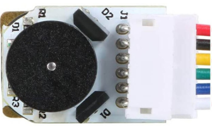
Pin Configuration and Descriptions

Pin Number Description Notes
1 Motor Power (+) Connect to positive voltage
2 Motor Power (-) Connect to ground
3 Encoder Vcc Encoder power supply (3.3V-5V)
4 Encoder GND Encoder ground
5 Encoder Channel A Outputs pulses for speed/position
6 Encoder Channel B Outputs pulses for direction

Usage Instructions

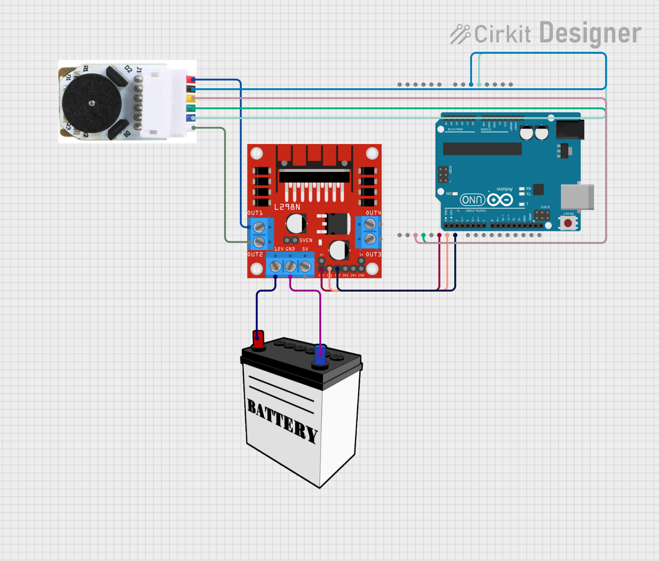
Connecting the Motor

  1. Connect the motor power pins to your power supply, ensuring the voltage is within the motor's rated specifications.
  2. Connect the encoder Vcc to a 3.3V or 5V supply from your microcontroller (e.g., Arduino UNO).
  3. Connect the encoder GND to the ground of your microcontroller.

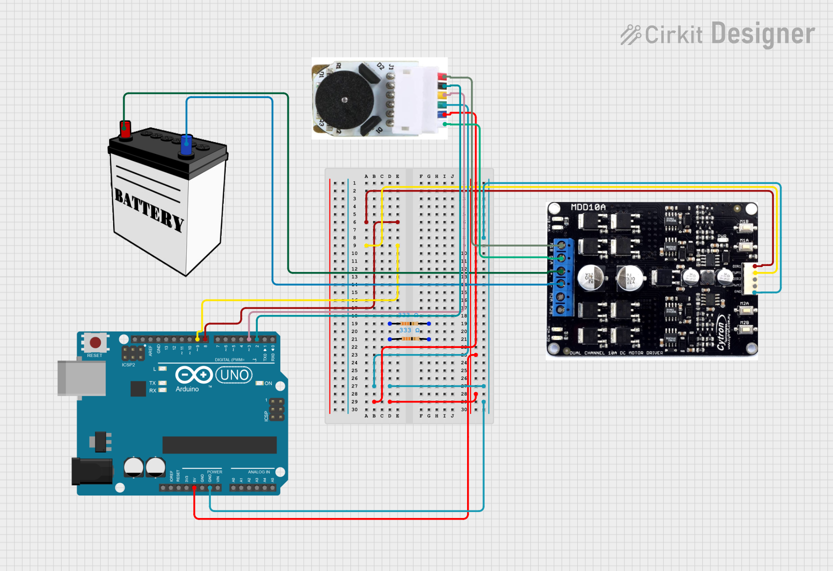
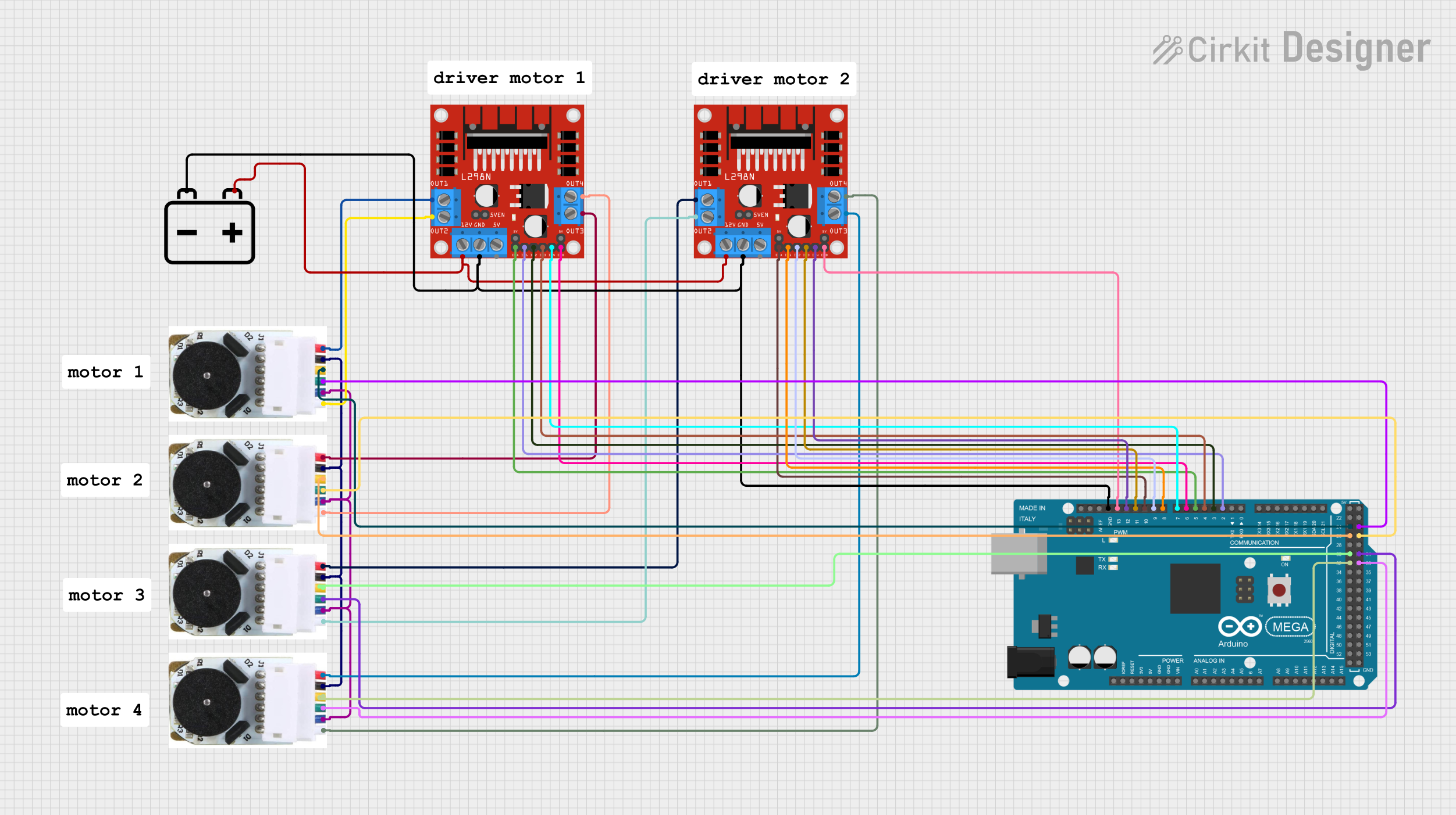
Interfacing with a Microcontroller

To use the motor with an Arduino UNO, you'll need to connect the encoder output pins to two digital input pins on the Arduino. You can use the attachInterrupt() function to count the pulses from the encoder, which represent the motor's rotation.

Sample Arduino Code

// Define the encoder pins
const int encoderPinA = 2; // Interrupt pin for encoder A
const int encoderPinB = 3; // Interrupt pin for encoder B

volatile long encoderTicks = 0;

// Interrupt service routine for encoder A
void encoderISR() {
  if (digitalRead(encoderPinB) == HIGH) {
    encoderTicks++;
  } else {
    encoderTicks--;
  }
}

void setup() {
  pinMode(encoderPinA, INPUT);
  pinMode(encoderPinB, INPUT);
  // Attach interrupt on a rising edge of encoder A (to call encoderISR)
  attachInterrupt(digitalPinToInterrupt(encoderPinA), encoderISR, RISING);
  Serial.begin(9600);
}

void loop() {
  Serial.println(encoderTicks);
  delay(1000); // Update every second
}

Important Considerations and Best Practices

  • Ensure the power supply does not exceed the motor's voltage rating to prevent damage.
  • Use a motor driver or H-bridge to control the motor's direction and speed.
  • Implement debounce logic in software or hardware to ensure accurate encoder readings.
  • Consider using a pull-up or pull-down resistor on the encoder outputs to stabilize the signal.

Troubleshooting and FAQs

Common Issues

  • Motor not turning: Check power supply connections and voltage levels.
  • Inaccurate encoder readings: Verify the encoder connections and ensure there are no loose wires. Implement debounce logic if necessary.
  • Motor turning erratically: Ensure that the motor driver is functioning correctly and that the PWM signal is stable.

FAQs

Q: How do I reverse the motor's direction? A: Use an H-bridge or motor driver to reverse the polarity of the voltage applied to the motor.

Q: Can I use this motor at a voltage lower than the rated voltage? A: Yes, but the motor will run slower and with less torque.

Q: How do I calculate the motor's position from the encoder? A: Count the number of encoder pulses and consider the encoder's resolution and the motor's gear ratio to determine the position.

Q: What is the purpose of having two channels on the encoder? A: Two channels allow for detecting the direction of rotation by comparing the phase of the signals.

For further assistance, consult the manufacturer's datasheet or contact technical support.