How to Use Voltage Protector: Examples, Pinouts, and Specs
Introduction
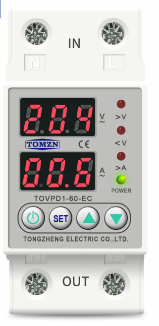
The Voltage Protector is a device designed to safeguard electrical circuits from voltage spikes, surges, and other irregularities. By regulating and limiting excessive voltage, it ensures the safety and longevity of connected components. This component is commonly used in power supply systems, sensitive electronic devices, and industrial equipment to prevent damage caused by transient voltage events.
Explore Projects Built with Voltage Protector


Explore Projects Built with Voltage Protector
Common Applications and Use Cases
- Protection of home appliances from power surges
- Safeguarding industrial machinery and equipment
- Ensuring stable voltage for sensitive electronics
- Use in renewable energy systems (e.g., solar inverters)
- Integration into automotive electrical systems
Technical Specifications
The Voltage Protector is available in various models, but the following are typical specifications for a standard unit:
| Parameter | Value |
|---|---|
| Operating Voltage Range | 100V - 250V AC |
| Maximum Surge Voltage | 600V |
| Response Time | < 1 nanosecond |
| Maximum Load Current | 10A |
| Power Rating | 2500W |
| Operating Temperature | -20°C to 70°C |
| Dimensions | 50mm x 30mm x 20mm |
| Mounting Type | PCB or inline connection |
Pin Configuration and Descriptions
The Voltage Protector typically has three pins or terminals for connection:
| Pin/Terminal | Name | Description |
|---|---|---|
| 1 | Input (Live) | Connects to the live wire of the input power source. |
| 2 | Output (Live) | Connects to the live wire of the load or protected device. |
| 3 | Neutral | Connects to the neutral wire of the input power source and the load. |
Usage Instructions
How to Use the Voltage Protector in a Circuit
- Identify the Input and Output Terminals: Ensure you correctly identify the input (live) and output (live) terminals, as well as the neutral terminal.
- Connect to the Power Source: Attach the input terminal to the live wire of the power source and the neutral terminal to the neutral wire.
- Connect the Load: Attach the output terminal to the live wire of the device or circuit you want to protect. Ensure the neutral wire of the load is also connected to the neutral terminal.
- Secure the Connections: Use proper insulation and secure the connections to avoid short circuits or loose wiring.
- Power On: Once all connections are verified, power on the system. The Voltage Protector will automatically regulate and protect against voltage surges.
Important Considerations and Best Practices
- Check the Ratings: Ensure the Voltage Protector's voltage and current ratings match the requirements of your circuit or device.
- Avoid Overloading: Do not exceed the maximum load current or power rating to prevent damage to the protector.
- Proper Grounding: Ensure the system is properly grounded to enhance protection against surges.
- Test Before Use: Test the protector with a multimeter to verify functionality before connecting sensitive devices.
- Use in Dry Environments: Avoid using the Voltage Protector in wet or humid conditions unless it is specifically rated for such environments.
Example: Using a Voltage Protector with an Arduino UNO
When connecting an Arduino UNO to a power source that may experience voltage fluctuations, a Voltage Protector can be used to ensure stable operation. Below is an example of how to integrate it:
- Connect the Voltage Protector's input terminals to the power source (e.g., a 12V adapter).
- Connect the output terminals to the Arduino UNO's power input (VIN and GND pins).
- Verify the connections and power on the system.
Here is a simple Arduino code snippet to test the functionality of the Arduino after integrating the Voltage Protector:
// Simple LED Blink Test for Arduino UNO
// This code ensures the Arduino is functioning correctly after using a Voltage Protector.

const int ledPin = 13; // Built-in LED pin on Arduino UNO

void setup() {
  pinMode(ledPin, OUTPUT); // Set the LED pin as an output
}

void loop() {
  digitalWrite(ledPin, HIGH); // Turn the LED on
  delay(1000);                // Wait for 1 second
  digitalWrite(ledPin, LOW);  // Turn the LED off
  delay(1000);                // Wait for 1 second
}
Troubleshooting and FAQs
Common Issues and Solutions
| Issue | Possible Cause | Solution |
|---|---|---|
| Device does not power on after connection | Incorrect wiring or loose connections | Double-check the wiring and ensure all connections are secure. |
| Voltage Protector overheats | Overloading or prolonged high voltage | Ensure the load does not exceed the protector's maximum current or power rating. |
| Protected device still experiences surges | Faulty Voltage Protector or improper grounding | Test the protector with a multimeter and verify proper grounding. |
| Protector trips frequently | Input voltage is outside the operating range | Verify the input voltage and ensure it is within the specified range. |
FAQs
Can the Voltage Protector handle DC voltage?
- Some models are designed for DC applications, but this documentation focuses on AC voltage protectors. Check the specifications of your specific model.
What happens if the Voltage Protector fails?
- Most protectors are designed to fail in a safe mode, disconnecting the load to prevent damage. However, it is recommended to replace a failed protector immediately.
Can I use multiple Voltage Protectors in parallel?
- It is generally unnecessary to use multiple protectors in parallel. If additional protection is required, consider using a higher-rated protector or combining it with other surge protection devices.
How do I test if the Voltage Protector is working?
- Use a multimeter to measure the output voltage under normal conditions. If the output voltage matches the expected value and the protector trips during a surge, it is functioning correctly.