Cirkit Designer Logo
Cirkit Designer
Your all-in-one circuit design IDE
Home / 
Component Documentation

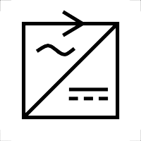
How to Use AC to DC: Examples, Pinouts, and Specs

Image of AC to DC
Cirkit Designer LogoDesign with AC to DC in Cirkit Designer

Introduction

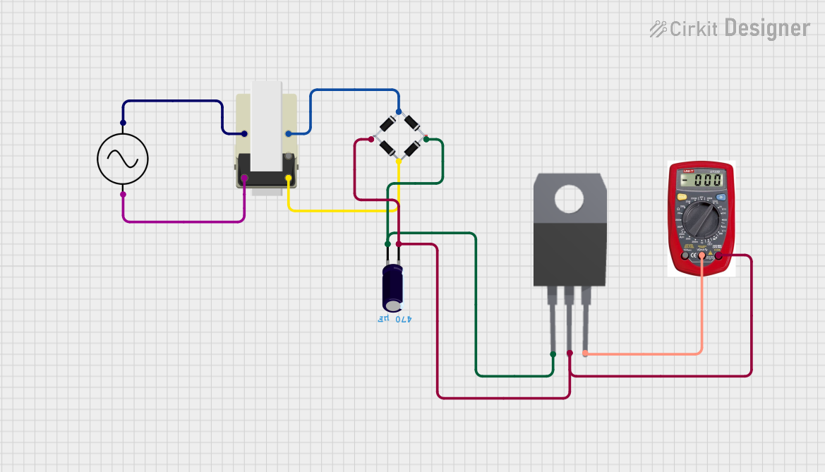
An AC to DC converter is an essential electronic component that transforms alternating current (AC) into direct current (DC). This conversion is crucial for powering various electronic devices and systems that require a stable DC voltage. AC to DC converters are commonly found in power supplies for consumer electronics, industrial equipment, and automotive applications.

Explore Projects Built with AC to DC

Use Cirkit Designer to design, explore, and prototype these projects online. Some projects support real-time simulation. Click "Open Project" to start designing instantly!
AC to DC Micro USB Power Supply with Buck Converter
Image of ac: A project utilizing AC to DC in a practical application
This circuit is designed to convert AC power to regulated DC power. An AC source feeds a power transformer that steps down the voltage, which is then rectified by a bridge rectifier to produce a pulsating DC. This DC is further converted to a stable DC output by a step-down buck converter, which then provides power through a Micro USB connector.
Cirkit Designer LogoOpen Project in Cirkit Designer
Battery-Powered USB Charger with LED Indicator and DC Motor
Image of Copy of Hand Crank mobile charger : A project utilizing AC to DC in a practical application
This circuit converts AC power to DC using a bridge rectifier and regulates the voltage to 5V with a 7805 voltage regulator. It powers a USB port and indicates power status with an LED, while also providing a charging interface through a multi-charging cable.
Cirkit Designer LogoOpen Project in Cirkit Designer
AC to DC Power Supply with Voltage Regulation and Multimeter Monitoring
Image of Copy of 8 volt AC to DC convertor (1): A project utilizing AC to DC in a practical application
This circuit is a power supply that converts AC voltage to a regulated DC output. An AC supply is connected to a transformer, which steps down the voltage to a lower AC voltage. This lower AC voltage is then rectified by a bridge rectifier into pulsating DC, filtered by an electrolytic capacitor to reduce ripple, and finally regulated by a 7808 voltage regulator to provide a stable 8V DC output. A multimeter is connected to measure the output voltage of the regulator.
Cirkit Designer LogoOpen Project in Cirkit Designer
AC to DC Power Supply with Transformer and Bridge Rectifier
Image of BRIDGE RECTIFIER: A project utilizing AC to DC in a practical application
This circuit is a basic AC to DC power supply that steps down 220V AC to a lower voltage using a transformer, rectifies it to DC using a bridge rectifier made of diodes, and smooths the output with an electrolytic capacitor. A rocker switch is used to turn the power supply on and off.
Cirkit Designer LogoOpen Project in Cirkit Designer

Explore Projects Built with AC to DC

Use Cirkit Designer to design, explore, and prototype these projects online. Some projects support real-time simulation. Click "Open Project" to start designing instantly!
Image of ac: A project utilizing AC to DC in a practical application
AC to DC Micro USB Power Supply with Buck Converter
This circuit is designed to convert AC power to regulated DC power. An AC source feeds a power transformer that steps down the voltage, which is then rectified by a bridge rectifier to produce a pulsating DC. This DC is further converted to a stable DC output by a step-down buck converter, which then provides power through a Micro USB connector.
Cirkit Designer LogoOpen Project in Cirkit Designer
Image of Copy of Hand Crank mobile charger : A project utilizing AC to DC in a practical application
Battery-Powered USB Charger with LED Indicator and DC Motor
This circuit converts AC power to DC using a bridge rectifier and regulates the voltage to 5V with a 7805 voltage regulator. It powers a USB port and indicates power status with an LED, while also providing a charging interface through a multi-charging cable.
Cirkit Designer LogoOpen Project in Cirkit Designer
Image of Copy of 8 volt AC to DC convertor (1): A project utilizing AC to DC in a practical application
AC to DC Power Supply with Voltage Regulation and Multimeter Monitoring
This circuit is a power supply that converts AC voltage to a regulated DC output. An AC supply is connected to a transformer, which steps down the voltage to a lower AC voltage. This lower AC voltage is then rectified by a bridge rectifier into pulsating DC, filtered by an electrolytic capacitor to reduce ripple, and finally regulated by a 7808 voltage regulator to provide a stable 8V DC output. A multimeter is connected to measure the output voltage of the regulator.
Cirkit Designer LogoOpen Project in Cirkit Designer
Image of BRIDGE RECTIFIER: A project utilizing AC to DC in a practical application
AC to DC Power Supply with Transformer and Bridge Rectifier
This circuit is a basic AC to DC power supply that steps down 220V AC to a lower voltage using a transformer, rectifies it to DC using a bridge rectifier made of diodes, and smooths the output with an electrolytic capacitor. A rocker switch is used to turn the power supply on and off.
Cirkit Designer LogoOpen Project in Cirkit Designer

Technical Specifications

Key Technical Details

Parameter Value
Input Voltage 100-240V AC
Output Voltage 5V, 12V, 24V DC (varies)
Output Current 1A, 2A, 5A (varies)
Power Rating 5W, 12W, 24W (varies)
Efficiency 85-95%
Ripple & Noise < 50mV
Operating Temp. -20°C to 70°C
Storage Temp. -40°C to 85°C
Humidity 0% to 95% RH (non-condensing)

Pin Configuration and Descriptions

Pin Number Pin Name Description
1 AC IN AC input terminal (L)
2 AC IN AC input terminal (N)
3 GND Ground terminal
4 DC OUT+ Positive DC output terminal
5 DC OUT- Negative DC output terminal

Usage Instructions

How to Use the Component in a Circuit

  1. Safety First: Ensure the power is turned off before making any connections.
  2. Connect AC Input: Connect the AC input terminals (L and N) to the AC power source.
  3. Connect DC Output: Connect the DC output terminals (DC OUT+ and DC OUT-) to the load or device that requires DC power.
  4. Grounding: Ensure the ground terminal (GND) is properly connected to avoid any electrical hazards.
  5. Power On: Once all connections are secure, turn on the AC power source.

Important Considerations and Best Practices

  • Voltage Rating: Ensure the input voltage matches the converter's rated input voltage.
  • Current Rating: Do not exceed the maximum output current rating to avoid damage.
  • Heat Dissipation: Provide adequate ventilation or cooling to prevent overheating.
  • Polarity: Double-check the polarity of the DC output connections to avoid damaging the connected device.
  • Isolation: Use isolation techniques if the converter is part of a sensitive or critical system.

Troubleshooting and FAQs

Common Issues Users Might Face

  1. No Output Voltage:

    • Solution: Check the AC input connections and ensure the power source is active. Verify that the converter is not in a fault condition.
  2. Overheating:

    • Solution: Ensure proper ventilation and cooling. Check if the load exceeds the converter's power rating.
  3. Output Voltage Fluctuations:

    • Solution: Verify the stability of the AC input voltage. Check for any loose connections or excessive load.
  4. Noise and Ripple:

    • Solution: Use additional filtering capacitors at the output. Ensure the converter is not operating near its maximum load capacity.

FAQs

Q1: Can I use an AC to DC converter with an Arduino UNO?

  • A1: Yes, you can use an AC to DC converter to power an Arduino UNO. Ensure the output voltage matches the Arduino's input voltage requirements (typically 5V or 9V).

Q2: What happens if I reverse the polarity of the DC output?

  • A2: Reversing the polarity can damage the connected device. Always double-check the polarity before powering on.

Q3: How do I know if the converter is faulty?

  • A3: If there is no output voltage despite correct connections and a stable input, the converter may be faulty. Check for any visible damage or overheating signs.

Q4: Can I use the converter in a high-humidity environment?

  • A4: Most converters are designed to operate in non-condensing environments. Ensure the humidity level is within the specified range (0% to 95% RH).

Example Code for Arduino UNO

Here is an example of how to use an AC to DC converter to power an Arduino UNO and blink an LED:

// Example code to blink an LED using Arduino UNO powered by an AC to DC converter

const int ledPin = 13; // Pin number for the LED

void setup() {
  pinMode(ledPin, OUTPUT); // Set the LED pin as an output
}

void loop() {
  digitalWrite(ledPin, HIGH); // Turn the LED on
  delay(1000); // Wait for 1 second
  digitalWrite(ledPin, LOW); // Turn the LED off
  delay(1000); // Wait for 1 second
}

Note: Ensure the AC to DC converter's output voltage matches the Arduino UNO's input voltage requirements.

This documentation provides a comprehensive guide to understanding, using, and troubleshooting an AC to DC converter. Whether you are a beginner or an experienced user, following these guidelines will help you effectively integrate this component into your projects.