Cirkit Designer Logo
Cirkit Designer
Your all-in-one circuit design IDE
Home / 
Component Documentation

How to Use orp sensor: Examples, Pinouts, and Specs

Image of orp sensor
Cirkit Designer LogoDesign with orp sensor in Cirkit Designer

Introduction

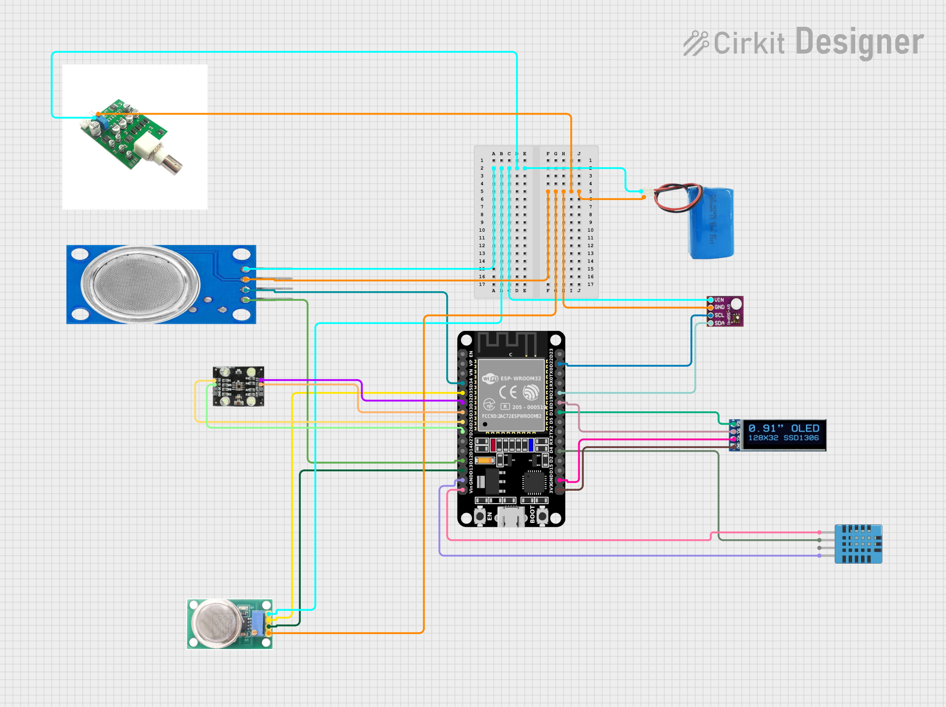
An ORP (Oxidation-Reduction Potential) sensor measures the cleanliness of water and its ability to break down contaminants. It provides a quantitative value for the water's oxidation-reduction potential, which is an essential parameter in water quality analysis. ORP sensors are widely used in applications such as water treatment, aquariums, swimming pools, and environmental monitoring.

Explore Projects Built with orp sensor

Use Cirkit Designer to design, explore, and prototype these projects online. Some projects support real-time simulation. Click "Open Project" to start designing instantly!
Battery-Powered Force Sensing System with nRF52840 and OPA688P
Image of BCT-BLE-Sensor: A project utilizing orp sensor in a practical application
This circuit is a sensor interface system that uses a Seeed Studio nRF52840 microcontroller to process signals from a force sensing resistor and a rotary potentiometer. The OPA688P operational amplifier conditions the sensor signals, which are then read by the microcontroller for further processing or transmission.
Cirkit Designer LogoOpen Project in Cirkit Designer
ESP32-Based Air Quality Monitoring Station with BMP280, SGP41, and PMS5003 Sensors
Image of indoor-sensors-v6: A project utilizing orp sensor in a practical application
This circuit is designed for environmental sensing and monitoring, featuring multiple sensors including a BMP280 for barometric pressure and temperature, a SenseAir S8 for CO2 levels, a PMS5003 for particulate matter, and an SGP41 for VOC and NOx levels. These sensors are interfaced with an ESP32 microcontroller, which likely serves as the central processing unit to collect, process, and possibly transmit sensor data. The ESP32 is connected to the sensors using I2C (SDA/SCL lines) and serial communication (RX/TX lines), and it provides power to the sensors (3V3/VIN lines).
Cirkit Designer LogoOpen Project in Cirkit Designer
ESP8266-Based Health Monitoring System with OLED Display
Image of Human Health Monitoring System Using IOT System: A project utilizing orp sensor in a practical application
This circuit is a multi-sensor data acquisition system using an ESP8266 NodeMCU microcontroller. It integrates a MAX30100 pulse oximeter, a BMP180 barometric pressure sensor, a DHT22 temperature and humidity sensor, and a 0.96" OLED display for real-time data visualization. The sensors communicate with the microcontroller via I2C and digital interfaces, and the collected data is displayed on the OLED screen.
Cirkit Designer LogoOpen Project in Cirkit Designer
ESP32-Based Environmental Monitoring System with Multiple Sensors and OLED Display
Image of meat_spoilage: A project utilizing orp sensor in a practical application
This circuit is an environmental monitoring system that uses an ESP32 microcontroller to collect data from various sensors, including gas sensors (MQ-135, MQ-136), a humidity and temperature sensor (DHT11), a VOC and NOx sensor (SGP41), and a color sensor (TCS230). The collected data is displayed on an OLED screen and can be transmitted via Bluetooth, with the ESP32 also handling RF signal decoding and transmission.
Cirkit Designer LogoOpen Project in Cirkit Designer

Explore Projects Built with orp sensor

Use Cirkit Designer to design, explore, and prototype these projects online. Some projects support real-time simulation. Click "Open Project" to start designing instantly!
Image of BCT-BLE-Sensor: A project utilizing orp sensor in a practical application
Battery-Powered Force Sensing System with nRF52840 and OPA688P
This circuit is a sensor interface system that uses a Seeed Studio nRF52840 microcontroller to process signals from a force sensing resistor and a rotary potentiometer. The OPA688P operational amplifier conditions the sensor signals, which are then read by the microcontroller for further processing or transmission.
Cirkit Designer LogoOpen Project in Cirkit Designer
Image of indoor-sensors-v6: A project utilizing orp sensor in a practical application
ESP32-Based Air Quality Monitoring Station with BMP280, SGP41, and PMS5003 Sensors
This circuit is designed for environmental sensing and monitoring, featuring multiple sensors including a BMP280 for barometric pressure and temperature, a SenseAir S8 for CO2 levels, a PMS5003 for particulate matter, and an SGP41 for VOC and NOx levels. These sensors are interfaced with an ESP32 microcontroller, which likely serves as the central processing unit to collect, process, and possibly transmit sensor data. The ESP32 is connected to the sensors using I2C (SDA/SCL lines) and serial communication (RX/TX lines), and it provides power to the sensors (3V3/VIN lines).
Cirkit Designer LogoOpen Project in Cirkit Designer
Image of Human Health Monitoring System Using IOT System: A project utilizing orp sensor in a practical application
ESP8266-Based Health Monitoring System with OLED Display
This circuit is a multi-sensor data acquisition system using an ESP8266 NodeMCU microcontroller. It integrates a MAX30100 pulse oximeter, a BMP180 barometric pressure sensor, a DHT22 temperature and humidity sensor, and a 0.96" OLED display for real-time data visualization. The sensors communicate with the microcontroller via I2C and digital interfaces, and the collected data is displayed on the OLED screen.
Cirkit Designer LogoOpen Project in Cirkit Designer
Image of meat_spoilage: A project utilizing orp sensor in a practical application
ESP32-Based Environmental Monitoring System with Multiple Sensors and OLED Display
This circuit is an environmental monitoring system that uses an ESP32 microcontroller to collect data from various sensors, including gas sensors (MQ-135, MQ-136), a humidity and temperature sensor (DHT11), a VOC and NOx sensor (SGP41), and a color sensor (TCS230). The collected data is displayed on an OLED screen and can be transmitted via Bluetooth, with the ESP32 also handling RF signal decoding and transmission.
Cirkit Designer LogoOpen Project in Cirkit Designer

Common Applications and Use Cases

  • Monitoring water quality in aquariums and fish tanks
  • Ensuring proper disinfection in swimming pools and spas
  • Industrial water treatment and wastewater management
  • Environmental monitoring of natural water bodies
  • Laboratory experiments and research

Technical Specifications

Below are the key technical details for a typical ORP sensor:

Parameter Value
Measurement Range -2000 mV to +2000 mV
Accuracy ±5 mV
Response Time ≤10 seconds
Operating Temperature 0°C to 60°C
Storage Temperature -10°C to 60°C
Output Signal Analog voltage (mV)
Power Supply (if needed) 3.3V to 5V (for signal amplifier)

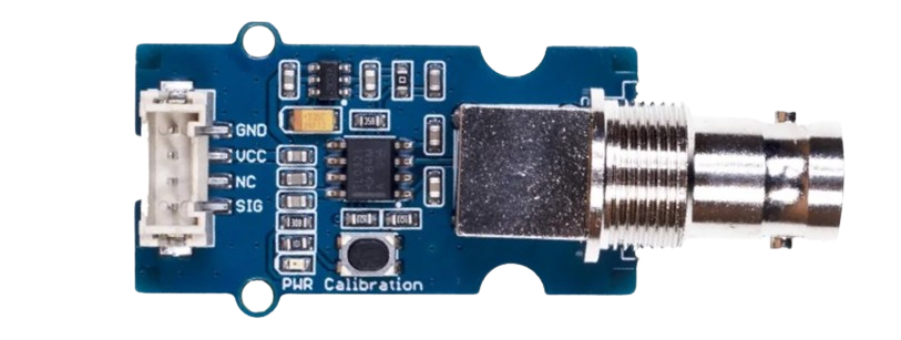
Pin Configuration and Descriptions

If the ORP sensor is used with a signal amplifier module, the pin configuration is as follows:

Pin Name Description
VCC Power supply input (3.3V to 5V)
GND Ground connection
OUT Analog output signal (ORP value in mV)

Usage Instructions

How to Use the ORP Sensor in a Circuit

  1. Connect the Sensor:

    • If using a signal amplifier module, connect the VCC pin to a 3.3V or 5V power source, the GND pin to ground, and the OUT pin to an analog input pin on your microcontroller (e.g., Arduino).
    • Submerge the ORP sensor probe in the water sample to be measured. Ensure the probe is fully immersed and avoid air bubbles around the sensing element.
  2. Calibrate the Sensor:

    • Use a standard ORP calibration solution (e.g., 225 mV or 475 mV) to calibrate the sensor for accurate readings.
    • Adjust the calibration potentiometer on the signal amplifier module (if available) to match the known ORP value of the solution.
  3. Read the Output:

    • The sensor outputs an analog voltage corresponding to the ORP value in millivolts (mV). Use an analog-to-digital converter (ADC) on your microcontroller to read the voltage and convert it to an ORP value.

Important Considerations and Best Practices

  • Probe Maintenance: Clean the ORP probe regularly to prevent fouling and ensure accurate readings.
  • Temperature Compensation: ORP readings can be affected by temperature. Use a temperature sensor for compensation if high accuracy is required.
  • Avoid Damage: Do not expose the probe to extreme temperatures or corrosive chemicals that could damage the sensing element.
  • Stabilization Time: Allow the sensor to stabilize for a few minutes after submersion before taking readings.

Example Code for Arduino UNO

Below is an example of how to interface an ORP sensor with an Arduino UNO:

// ORP Sensor Example Code for Arduino UNO
// Reads the analog output from the ORP sensor and converts it to mV

const int ORP_PIN = A0; // Analog pin connected to the sensor's OUT pin
float voltage;          // Variable to store the sensor's output voltage
float orpValue;         // Variable to store the calculated ORP value

void setup() {
  Serial.begin(9600); // Initialize serial communication at 9600 baud
  pinMode(ORP_PIN, INPUT); // Set the ORP pin as input
}

void loop() {
  int sensorValue = analogRead(ORP_PIN); // Read the analog value from the sensor
  voltage = sensorValue * (5.0 / 1023.0); // Convert ADC value to voltage (5V reference)
  
  // Convert voltage to ORP value in mV
  // Note: Adjust the offset (e.g., 1500) based on your sensor's calibration
  orpValue = (voltage * 1000) - 1500; 
  
  // Print the ORP value to the Serial Monitor
  Serial.print("ORP Value: ");
  Serial.print(orpValue);
  Serial.println(" mV");
  
  delay(1000); // Wait for 1 second before the next reading
}

Troubleshooting and FAQs

Common Issues and Solutions

  1. Inaccurate Readings:

    • Cause: Dirty or fouled probe.
    • Solution: Clean the probe with distilled water and a soft brush. Avoid abrasive materials.
  2. Fluctuating Readings:

    • Cause: Air bubbles around the probe or unstable power supply.
    • Solution: Ensure the probe is fully submerged without air bubbles. Use a stable power source.
  3. No Output Signal:

    • Cause: Incorrect wiring or damaged probe.
    • Solution: Verify the wiring connections and check the probe for physical damage.
  4. Slow Response Time:

    • Cause: Aging probe or low water temperature.
    • Solution: Replace the probe if it is old. Allow more time for the sensor to stabilize in cold water.

FAQs

Q1: Can the ORP sensor be used in seawater?
A1: Yes, most ORP sensors are compatible with seawater. However, ensure the probe material is resistant to corrosion.

Q2: How often should I calibrate the ORP sensor?
A2: Calibration frequency depends on usage. For critical applications, calibrate weekly. For general use, monthly calibration is sufficient.

Q3: What is a good ORP value for drinking water?
A3: A positive ORP value between +200 mV and +600 mV typically indicates good water quality.

Q4: Can I use the ORP sensor without a signal amplifier?
A4: It is possible, but the raw signal may be too weak or noisy. A signal amplifier is recommended for accurate readings.

By following this documentation, you can effectively use an ORP sensor for water quality monitoring and other applications.