
How to Use IO Expansion Shield for Arduino Nano: Examples, Pinouts, and Specs
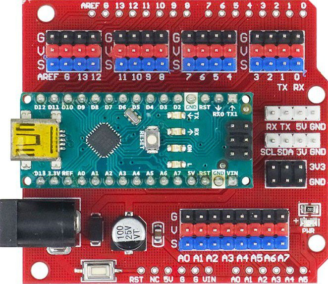
 Design with IO Expansion Shield for Arduino Nano in Cirkit Designer
Introduction
The IO Expansion Shield for Arduino Nano is a versatile add-on board designed to enhance the functionality of the Arduino Nano by providing additional input/output (I/O) pins. This shield simplifies the process of connecting multiple sensors, actuators, and other peripheral devices to the Nano, making it an ideal choice for projects requiring extensive connectivity. It also includes convenient features such as onboard power terminals, pin headers, and compatibility with various modules.
Explore Projects Built with IO Expansion Shield for Arduino Nano
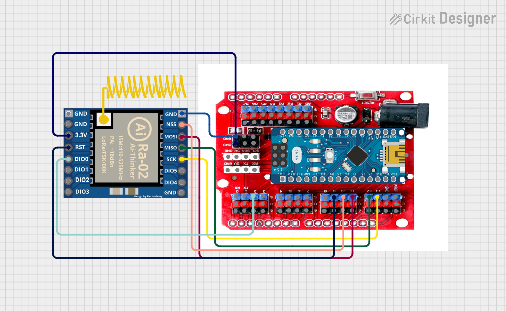 Open Project in Cirkit Designer
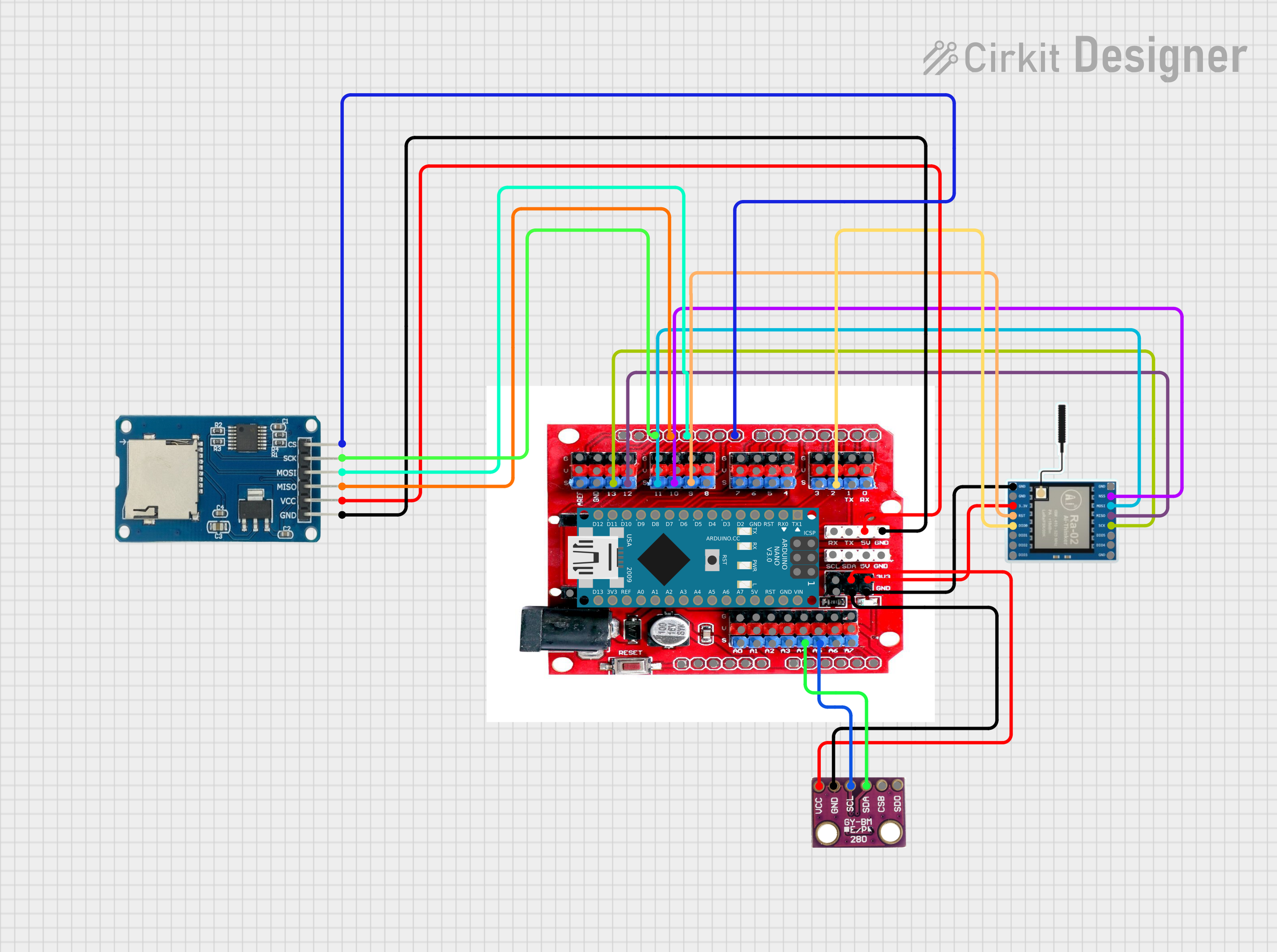 Open Project in Cirkit Designer
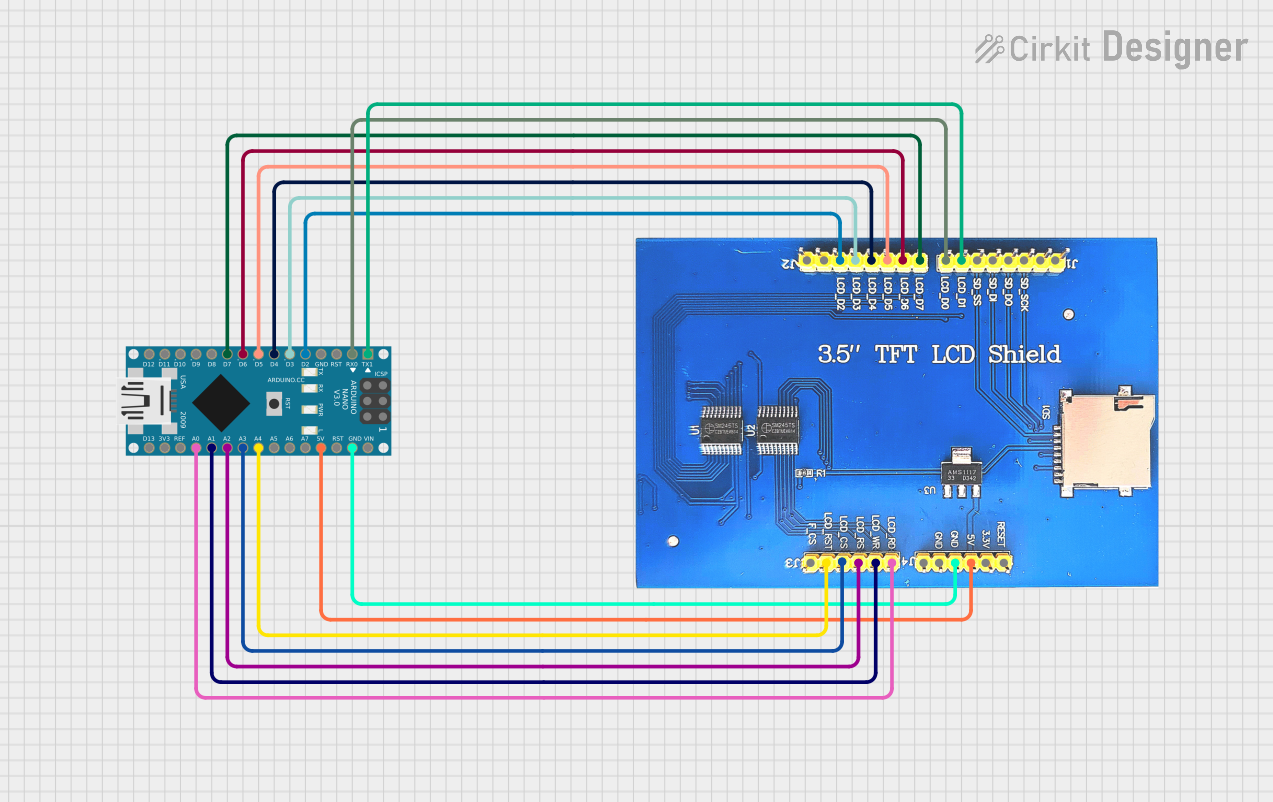 Open Project in Cirkit Designer
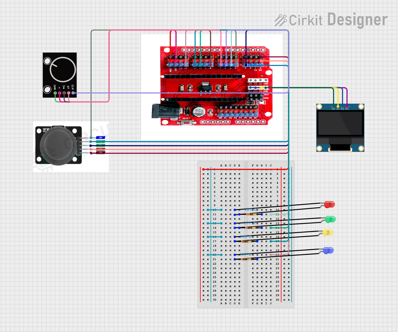 Open Project in Cirkit Designer
Explore Projects Built with IO Expansion Shield for Arduino Nano
Open Project in Cirkit DesignerOpen Project in Cirkit DesignerOpen Project in Cirkit DesignerOpen Project in Cirkit DesignerCommon Applications and Use Cases
- Robotics projects requiring multiple motor drivers and sensors
- Home automation systems with numerous input/output devices
- Prototyping and testing circuits with multiple components
- IoT (Internet of Things) applications with extensive peripheral connections
- Educational projects for learning microcontroller interfacing
Technical Specifications
- Compatible Microcontroller: Arduino Nano
- Operating Voltage: 5V (from Arduino Nano or external power supply)
- Input Voltage (External Power): 6V–12V DC
- I/O Pins: Breakout for all Arduino Nano pins
- Additional Features:
- Screw terminals for external power input
- Reset button for Arduino Nano
- Power and status LEDs
- 3.3V and 5V power output pins
- Female headers for easy module connections
- Dimensions: Matches the Arduino Nano footprint
Pin Configuration and Descriptions
The IO Expansion Shield breaks out all the pins of the Arduino Nano into easily accessible headers. Below is a table describing the pin configuration:
| Pin | Description |
|---|---|
| Digital Pins | D0–D13: Standard digital I/O pins for sensors, actuators, and other peripherals |
| Analog Pins | A0–A7: Analog input pins for reading sensor data |
| Power Pins | 5V, 3.3V, GND: Power output pins for external modules |
| Reset | Reset button to restart the Arduino Nano |
| Screw Terminals | External power input (6V–12V DC) |
Usage Instructions
How to Use the IO Expansion Shield in a Circuit
- Attach the Arduino Nano: Insert the Arduino Nano into the female headers on the shield, ensuring proper alignment of the pins.
- Connect External Power (Optional): If your project requires more power than the Arduino Nano can provide, connect an external power supply (6V–12V DC) to the screw terminals.
- Connect Peripherals: Use the breakout headers to connect sensors, actuators, or other devices to the appropriate pins (digital, analog, or power).
- Upload Code: Write and upload your Arduino sketch to the Nano using the Arduino IDE.
- Power On: Power the system via USB or the external power supply.
Important Considerations and Best Practices
- Power Supply: Ensure the external power supply voltage is within the specified range (6V–12V DC) to avoid damaging the shield or Arduino Nano.
- Pin Mapping: Double-check the pin mapping in your code to ensure proper connections to the shield's breakout pins.
- Avoid Overloading: Do not exceed the current limits of the Arduino Nano or the shield's power output pins.
- Secure Connections: Use jumper wires or soldered connections for reliable operation in permanent setups.
Example Code for Arduino Nano
Below is an example code snippet to demonstrate how to use the IO Expansion Shield to control an LED and read a sensor:
// Example code for IO Expansion Shield with Arduino Nano
// This code toggles an LED connected to pin D13 and reads an analog sensor on A0.

const int ledPin = 13;  // Digital pin for LED
const int sensorPin = A0;  // Analog pin for sensor
int sensorValue = 0;  // Variable to store sensor reading

void setup() {
  pinMode(ledPin, OUTPUT);  // Set LED pin as output
  pinMode(sensorPin, INPUT);  // Set sensor pin as input
  Serial.begin(9600);  // Initialize serial communication for debugging
}

void loop() {
  sensorValue = analogRead(sensorPin);  // Read sensor value
  Serial.print("Sensor Value: ");  // Print sensor value to Serial Monitor
  Serial.println(sensorValue);

  if (sensorValue > 512) {  // If sensor value exceeds threshold
    digitalWrite(ledPin, HIGH);  // Turn on LED
  } else {
    digitalWrite(ledPin, LOW);  // Turn off LED
  }

  delay(500);  // Wait for 500 milliseconds
}
Troubleshooting and FAQs
Common Issues and Solutions
Arduino Nano Not Powering On:
- Ensure the Nano is properly seated in the shield's headers.
- Check the power source (USB or external power supply) and connections.
Peripherals Not Responding:
- Verify the wiring and connections to the shield's breakout pins.
- Double-check the pin assignments in your Arduino code.
Overheating Components:
- Ensure the external power supply voltage is within the specified range (6V–12V DC).
- Avoid drawing excessive current from the power output pins.
Serial Communication Not Working:
- Confirm that the correct COM port is selected in the Arduino IDE.
- Ensure no other devices are using the same serial port.
FAQs
Q: Can I use the shield with other Arduino boards?
A: No, this shield is specifically designed for the Arduino Nano and may not be compatible with other Arduino boards.
Q: How many devices can I connect to the shield?
A: The number of devices depends on the available I/O pins and the power requirements of your peripherals.
Q: Can I power the shield and Nano using only USB?
A: Yes, but ensure the total current draw of your peripherals does not exceed the USB power limit (typically 500mA).
Q: Is the shield compatible with 3.3V devices?
A: Yes, the shield provides both 3.3V and 5V power output pins for compatibility with a wide range of devices.