How to Use SIM7600CE: Examples, Pinouts, and Specs
Introduction
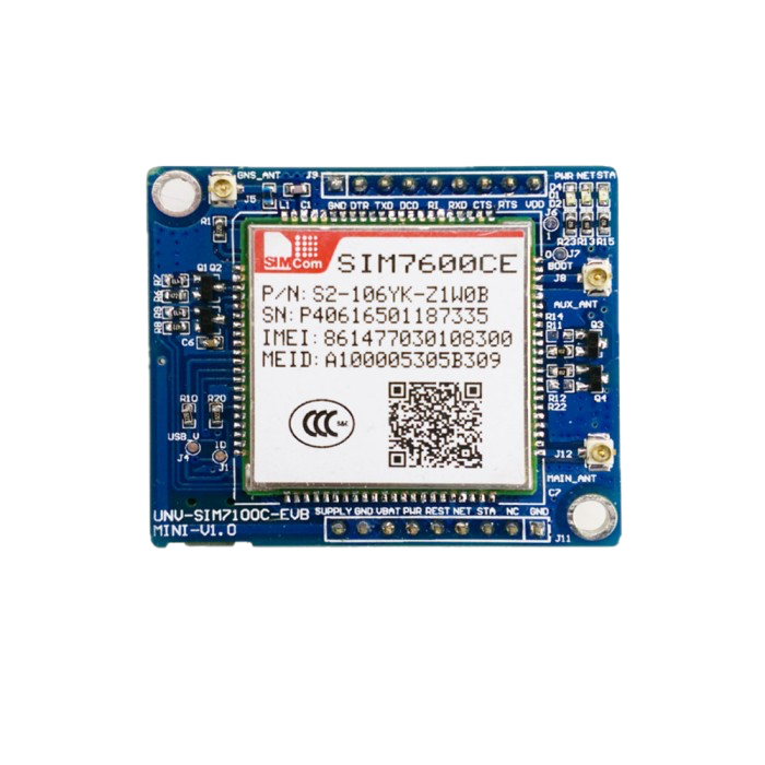
The SIM7600CE is a 4G LTE module that supports multiple communication protocols, including GSM, GPRS, and HSPA+. It is designed to provide high-speed data transfer and GPS functionality, making it an ideal choice for Internet of Things (IoT) applications. This module is widely used in remote monitoring, industrial automation, smart metering, vehicle tracking, and other applications requiring reliable wireless communication.
Explore Projects Built with SIM7600CE


Explore Projects Built with SIM7600CE
Common Applications:
- IoT devices and systems
- GPS-based vehicle tracking
- Remote monitoring and control
- Smart metering and telemetry
- Industrial automation
- Wireless payment terminals
Technical Specifications
Key Technical Details:
| Parameter | Value |
|---|---|
| Communication Protocols | LTE, GSM, GPRS, EDGE, WCDMA, HSPA+ |
| LTE Bands | B1/B3/B5/B8/B38/B39/B40/B41 |
| Operating Voltage | 3.4V to 4.2V |
| Power Consumption | Idle: ~20mA, Active: ~1.5A (peak) |
| GPS Support | Yes (GNSS: GPS, GLONASS, BeiDou, Galileo) |
| Data Rate (LTE) | Uplink: 50 Mbps, Downlink: 150 Mbps |
| Operating Temperature | -40°C to +85°C |
| Dimensions | 30mm x 30mm x 2.9mm |
| Interface | UART, USB, GPIO, I2C, SPI |
Pin Configuration and Descriptions:
| Pin Number | Pin Name | Description |
|---|---|---|
| 1 | VCC | Power supply input (3.4V to 4.2V) |
| 2 | GND | Ground |
| 3 | TXD | UART Transmit |
| 4 | RXD | UART Receive |
| 5 | USB_D+ | USB Data Positive |
| 6 | USB_D- | USB Data Negative |
| 7 | GPIO1 | General Purpose Input/Output |
| 8 | GPIO2 | General Purpose Input/Output |
| 9 | SIM_VDD | SIM card power supply |
| 10 | SIM_DATA | SIM card data |
| 11 | SIM_CLK | SIM card clock |
| 12 | SIM_RST | SIM card reset |
| 13 | GNSS_TXD | GNSS UART Transmit |
| 14 | GNSS_RXD | GNSS UART Receive |
| 15 | NET_STATUS | Network status indicator |
| 16 | PWRKEY | Power on/off control |
Usage Instructions
How to Use the SIM7600CE in a Circuit:
- Power Supply: Connect the VCC pin to a stable 3.7V power source and GND to ground. Ensure the power supply can handle peak currents of up to 2A.
- UART Communication: Connect the TXD and RXD pins to the corresponding UART pins of your microcontroller or development board (e.g., Arduino UNO).
- SIM Card: Insert a valid SIM card into the SIM card slot and connect the SIM_VDD, SIM_DATA, SIM_CLK, and SIM_RST pins as required.
- Antenna: Attach a 4G LTE antenna to the module's antenna connector for optimal signal reception.
- Power On: Use the PWRKEY pin to turn the module on or off. Pull the PWRKEY pin low for at least 1 second to power on the module.
Important Considerations:
- Use decoupling capacitors near the power supply pins to reduce noise and ensure stable operation.
- Ensure proper grounding to avoid communication issues.
- Use level shifters if interfacing with a 5V microcontroller, as the SIM7600CE operates at 3.3V logic levels.
- Place the antenna away from high-frequency components to minimize interference.
Example: Connecting SIM7600CE to Arduino UNO
Below is an example of how to send an SMS using the SIM7600CE module with an Arduino UNO:
Circuit Connections:
- SIM7600CE TXD → Arduino RX (Pin 0)
- SIM7600CE RXD → Arduino TX (Pin 1)
- SIM7600CE VCC → 3.7V Power Supply
- SIM7600CE GND → Arduino GND
Arduino Code:
#include <SoftwareSerial.h>

// Define RX and TX pins for SoftwareSerial
SoftwareSerial sim7600(10, 11); // RX = Pin 10, TX = Pin 11

void setup() {
  // Initialize serial communication with the SIM7600CE module
  sim7600.begin(9600);
  Serial.begin(9600);

  // Wait for the module to initialize
  delay(1000);
  Serial.println("Initializing SIM7600CE...");

  // Send AT command to check communication
  sim7600.println("AT");
  delay(1000);
  while (sim7600.available()) {
    Serial.write(sim7600.read());
  }

  // Set SMS text mode
  sim7600.println("AT+CMGF=1"); // Set SMS to text mode
  delay(1000);

  // Send SMS command
  sim7600.println("AT+CMGS=\"+1234567890\""); // Replace with recipient's number
  delay(1000);
  sim7600.println("Hello from SIM7600CE!"); // SMS content
  delay(1000);
  sim7600.write(26); // Send Ctrl+Z to send the SMS
}

void loop() {
  // Continuously read data from the SIM7600CE module
  if (sim7600.available()) {
    Serial.write(sim7600.read());
  }
}
Notes:
- Replace
+1234567890with the recipient's phone number. - Ensure the SIM card has sufficient balance and SMS services enabled.
Troubleshooting and FAQs
Common Issues and Solutions:
Module Not Powering On:
- Ensure the power supply provides a stable voltage between 3.4V and 4.2V.
- Check the PWRKEY pin connection and hold it low for at least 1 second to power on.
No Network Connection:
- Verify that the SIM card is properly inserted and activated.
- Check the antenna connection and ensure it is securely attached.
- Use the
AT+CSQcommand to check signal strength. A value above 10 is recommended.
UART Communication Issues:
- Confirm the baud rate matches between the SIM7600CE and the microcontroller.
- Use level shifters if the microcontroller operates at 5V logic levels.
GPS Not Working:
- Ensure the GNSS antenna is connected and placed in an open area with a clear view of the sky.
- Use the
AT+CGNSPWR=1command to enable GPS functionality.
FAQs:
Q: Can the SIM7600CE work with 5V microcontrollers?
A: Yes, but you need level shifters to convert 5V logic to 3.3V logic.Q: How do I check the module's firmware version?
A: Use theAT+CGMRcommand to retrieve the firmware version.Q: What is the maximum data rate supported by the SIM7600CE?
A: The module supports up to 150 Mbps downlink and 50 Mbps uplink on LTE networks.Q: Can I use the SIM7600CE for voice calls?
A: Yes, the module supports voice calls. Use theATDcommand to dial a number.
By following this documentation, you can effectively integrate the SIM7600CE module into your projects and troubleshoot common issues.