Cirkit Designer Logo
Cirkit Designer
Your all-in-one circuit design IDE
Home / 
Component Documentation

How to Use RPLIDAR A1M8 - R6: Examples, Pinouts, and Specs

Image of RPLIDAR A1M8 - R6
Cirkit Designer LogoDesign with RPLIDAR A1M8 - R6 in Cirkit Designer

Introduction

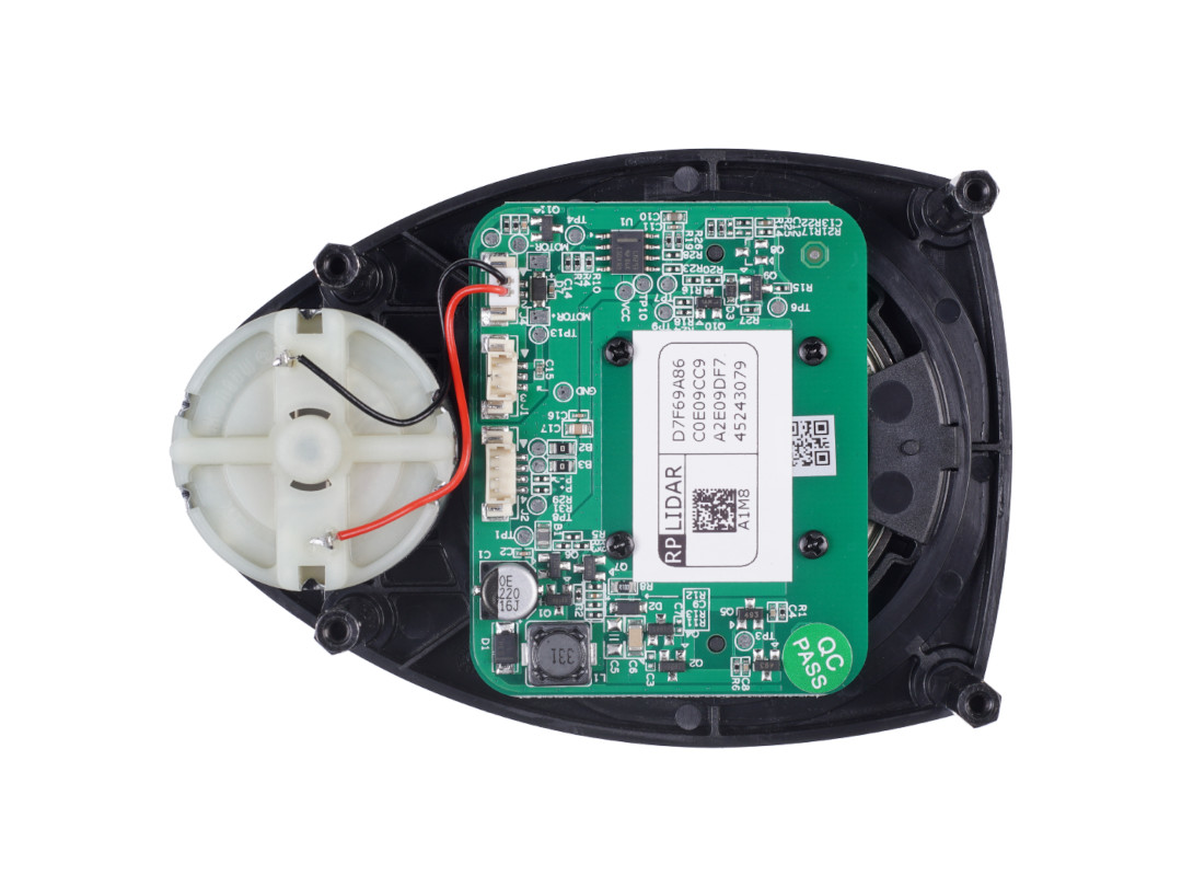
The RPLIDAR A1M8 - R6, manufactured by Slamtec, is a 360-degree laser scanner designed for mapping, navigation, and object detection in robotics and automation systems. This compact and lightweight LiDAR sensor provides high-resolution distance measurements, making it ideal for applications such as autonomous robots, drones, and indoor mapping. Its ability to operate in various environments ensures reliable performance in diverse use cases.

Explore Projects Built with RPLIDAR A1M8 - R6

Use Cirkit Designer to design, explore, and prototype these projects online. Some projects support real-time simulation. Click "Open Project" to start designing instantly!
Arduino Mega-Controlled Robotic Vehicle with RF Communication and Sensor Integration
Image of Copy of Copy of Beach-Bot: A project utilizing RPLIDAR A1M8 - R6 in a practical application
This circuit is designed for advanced motion control and environmental sensing, featuring motor control with feedback, distance measurement, and wireless communication. It is powered by renewable energy sources, making it suitable for autonomous, remote, or outdoor applications. The lack of embedded code indicates that the control logic for the system's operation is not yet implemented.
Cirkit Designer LogoOpen Project in Cirkit Designer
Satellite-Based Timing and Navigation System with SDR and Atomic Clock Synchronization
Image of GPS 시스템 측정 구성도_Confirm: A project utilizing RPLIDAR A1M8 - R6 in a practical application
This circuit appears to be a complex system involving power supply management, GPS and timing synchronization, and data communication. It includes a SI-TEX G1 Satellite Compass for GPS data, an XHTF1021 Atomic Rubidium Clock for precise timing, and Ettus USRP B200 units for software-defined radio communication. Power is supplied through various SMPS units and distributed via terminal blocks and DC jacks. Data communication is facilitated by Beelink MINI S12 N95 computers, RS232 splitters, and a 1000BASE-T Media Converter for network connectivity. RF Directional Couplers are used to interface antennas with the USRP units, and the entire system is likely contained within cases for protection and organization.
Cirkit Designer LogoOpen Project in Cirkit Designer
Arduino UNO with A9G GSM/GPRS and Dual VL53L1X Distance Sensors
Image of TED CIRCUIT : A project utilizing RPLIDAR A1M8 - R6 in a practical application
This circuit features an Arduino UNO microcontroller interfaced with an A9G GSM/GPRS+GPS/BDS module and two VL53L1X time-of-flight distance sensors. The A9G module is connected to the Arduino via serial communication for GPS and GSM functionalities, while both VL53L1X sensors are connected through I2C with shared SDA and SCL lines and individual SHUT pins for selective sensor activation. The Arduino is programmed to control these peripherals, although the specific functionality is not detailed in the provided code.
Cirkit Designer LogoOpen Project in Cirkit Designer
STM32F103C8T6-Based Access Control System with RFID and Servo Motor Actuation
Image of PARCEL SORTING SEM 5: A project utilizing RPLIDAR A1M8 - R6 in a practical application
This circuit features an STM32F103C8T6 microcontroller interfaced with an RFID-RC522 module for RFID reading, two servo motors, an IR sensor, and a 2-channel relay module controlling two hobby motors. The microcontroller manages the communication with the RFID module via SPI (MOSI, MISO, SCK, SDA), processes the IR sensor signal, and outputs PWM signals to the servo motors. The relay module is used to switch the hobby motors on and off, with the microcontroller providing control signals and power supplies providing the necessary voltage levels for the different components.
Cirkit Designer LogoOpen Project in Cirkit Designer

Explore Projects Built with RPLIDAR A1M8 - R6

Use Cirkit Designer to design, explore, and prototype these projects online. Some projects support real-time simulation. Click "Open Project" to start designing instantly!
Image of Copy of Copy of Beach-Bot: A project utilizing RPLIDAR A1M8 - R6 in a practical application
Arduino Mega-Controlled Robotic Vehicle with RF Communication and Sensor Integration
This circuit is designed for advanced motion control and environmental sensing, featuring motor control with feedback, distance measurement, and wireless communication. It is powered by renewable energy sources, making it suitable for autonomous, remote, or outdoor applications. The lack of embedded code indicates that the control logic for the system's operation is not yet implemented.
Cirkit Designer LogoOpen Project in Cirkit Designer
Image of GPS 시스템 측정 구성도_Confirm: A project utilizing RPLIDAR A1M8 - R6 in a practical application
Satellite-Based Timing and Navigation System with SDR and Atomic Clock Synchronization
This circuit appears to be a complex system involving power supply management, GPS and timing synchronization, and data communication. It includes a SI-TEX G1 Satellite Compass for GPS data, an XHTF1021 Atomic Rubidium Clock for precise timing, and Ettus USRP B200 units for software-defined radio communication. Power is supplied through various SMPS units and distributed via terminal blocks and DC jacks. Data communication is facilitated by Beelink MINI S12 N95 computers, RS232 splitters, and a 1000BASE-T Media Converter for network connectivity. RF Directional Couplers are used to interface antennas with the USRP units, and the entire system is likely contained within cases for protection and organization.
Cirkit Designer LogoOpen Project in Cirkit Designer
Image of TED CIRCUIT : A project utilizing RPLIDAR A1M8 - R6 in a practical application
Arduino UNO with A9G GSM/GPRS and Dual VL53L1X Distance Sensors
This circuit features an Arduino UNO microcontroller interfaced with an A9G GSM/GPRS+GPS/BDS module and two VL53L1X time-of-flight distance sensors. The A9G module is connected to the Arduino via serial communication for GPS and GSM functionalities, while both VL53L1X sensors are connected through I2C with shared SDA and SCL lines and individual SHUT pins for selective sensor activation. The Arduino is programmed to control these peripherals, although the specific functionality is not detailed in the provided code.
Cirkit Designer LogoOpen Project in Cirkit Designer
Image of PARCEL SORTING SEM 5: A project utilizing RPLIDAR A1M8 - R6 in a practical application
STM32F103C8T6-Based Access Control System with RFID and Servo Motor Actuation
This circuit features an STM32F103C8T6 microcontroller interfaced with an RFID-RC522 module for RFID reading, two servo motors, an IR sensor, and a 2-channel relay module controlling two hobby motors. The microcontroller manages the communication with the RFID module via SPI (MOSI, MISO, SCK, SDA), processes the IR sensor signal, and outputs PWM signals to the servo motors. The relay module is used to switch the hobby motors on and off, with the microcontroller providing control signals and power supplies providing the necessary voltage levels for the different components.
Cirkit Designer LogoOpen Project in Cirkit Designer

Common Applications

  • Autonomous robot navigation and obstacle avoidance
  • Indoor mapping and 3D modeling
  • SLAM (Simultaneous Localization and Mapping) systems
  • Drones and UAVs for environmental scanning
  • Smart home and IoT devices requiring spatial awareness

Technical Specifications

The RPLIDAR A1M8 - R6 is a versatile and efficient LiDAR sensor with the following key specifications:

Parameter Value
Manufacturer Slamtec
Model A1M8-R6
Scanning Range 0.15 m to 12 m
Scanning Angle 360°
Angular Resolution 1° to 0.5° (adjustable based on speed)
Scanning Frequency 5 Hz to 10 Hz
Distance Resolution < 1% of the distance
Light Source 785 nm Infrared Laser (Class 1 Safety)
Communication Interface UART (3.3V TTL)
Input Voltage 5 V DC
Power Consumption 2 W (typical)
Dimensions 98.5 mm × 70 mm × 60 mm
Weight 190 g
Operating Temperature 0°C to 40°C

Pin Configuration and Descriptions

The RPLIDAR A1M8 - R6 uses a 5-pin connector for power and communication. Below is the pinout:

Pin Name Description
1 VCC 5 V DC input power
2 GND Ground
3 TX (UART) UART Transmit (3.3V TTL)
4 RX (UART) UART Receive (3.3V TTL)
5 MOTOCTL Motor control signal (PWM input)

Usage Instructions

Connecting the RPLIDAR A1M8 - R6

  1. Power Supply: Connect the VCC pin to a 5 V DC power source and the GND pin to ground.
  2. Communication: Use the TX and RX pins to establish a UART connection with a microcontroller or computer. Ensure the UART voltage level is 3.3V TTL.
  3. Motor Control: Use the MOTOCTL pin to control the motor speed via a PWM signal. A typical PWM frequency of 10 kHz is recommended.

Using with an Arduino UNO

To interface the RPLIDAR A1M8 - R6 with an Arduino UNO, you will need a logic level shifter to convert the 3.3V UART signals to 5V. Below is an example setup and code:

Wiring Diagram

RPLIDAR Pin Arduino Pin
VCC 5V
GND GND
TX RX (via level shifter)
RX TX (via level shifter)
MOTOCTL PWM-capable pin (e.g., D3)

Arduino Code Example

#include <RPLidar.h> // Include the RPLIDAR library

// Define RPLIDAR pins
#define RPLIDAR_MOTOR_PIN 3 // PWM pin for motor control
#define RPLIDAR_RX_PIN 10   // RX pin for UART communication
#define RPLIDAR_TX_PIN 11   // TX pin for UART communication

RPLidar lidar; // Create an RPLidar object

void setup() {
  // Initialize serial communication for debugging
  Serial.begin(115200);
  
  // Initialize RPLIDAR communication
  lidar.begin(Serial1); // Use Serial1 for hardware UART
  
  // Start the motor
  pinMode(RPLIDAR_MOTOR_PIN, OUTPUT);
  analogWrite(RPLIDAR_MOTOR_PIN, 255); // Set motor speed to maximum
}

void loop() {
  if (IS_OK(lidar.waitPoint())) {
    // Get the distance and angle of the current scan point
    float distance = lidar.getCurrentPoint().distance; // Distance in mm
    float angle = lidar.getCurrentPoint().angle;       // Angle in degrees
    
    // Print the data to the serial monitor
    Serial.print("Distance: ");
    Serial.print(distance);
    Serial.print(" mm, Angle: ");
    Serial.print(angle);
    Serial.println(" degrees");
  } else {
    // Handle errors or no data
    Serial.println("Error: Unable to read data from RPLIDAR.");
  }
}

Best Practices

  • Ensure the RPLIDAR is mounted on a stable surface to minimize vibrations.
  • Avoid exposing the sensor to direct sunlight or reflective surfaces, as these can interfere with measurements.
  • Use a logic level shifter when interfacing with 5V microcontrollers like the Arduino UNO.
  • Regularly clean the LiDAR lens to maintain accuracy.

Troubleshooting and FAQs

Common Issues

  1. No Data Output

    • Cause: Incorrect wiring or UART configuration.
    • Solution: Verify the TX and RX connections and ensure the baud rate matches the RPLIDAR's default (115200 bps).
  2. Motor Not Spinning

    • Cause: MOTOCTL pin not receiving a valid PWM signal.
    • Solution: Check the PWM signal on the MOTOCTL pin and ensure it is within the recommended frequency range.
  3. Inaccurate Measurements

    • Cause: Dirty lens or environmental interference.
    • Solution: Clean the lens and avoid reflective or direct sunlight in the scanning area.
  4. Overheating

    • Cause: Prolonged operation in high-temperature environments.
    • Solution: Ensure adequate ventilation and operate within the specified temperature range (0°C to 40°C).

FAQs

Q: Can the RPLIDAR A1M8 - R6 be used outdoors?
A: While it can operate outdoors, performance may degrade in direct sunlight or adverse weather conditions. It is primarily designed for indoor use.

Q: What is the maximum scanning range?
A: The RPLIDAR A1M8 - R6 can measure distances up to 12 meters under optimal conditions.

Q: Is the laser safe for human eyes?
A: Yes, the RPLIDAR uses a Class 1 laser, which is safe for human eyes under normal operation.

Q: Can I adjust the scanning speed?
A: Yes, the scanning frequency can be adjusted between 5 Hz and 10 Hz by modifying the motor control signal.

Q: Does the RPLIDAR support SLAM algorithms?
A: The RPLIDAR provides raw distance and angle data, which can be used with external SLAM algorithms for mapping and navigation.