How to Use serial_converter: Examples, Pinouts, and Specs
Introduction
A serial converter is a versatile electronic component designed to convert data between parallel and serial formats. This functionality enables seamless communication between devices that utilize different data transmission methods. Serial converters are commonly used in applications where data needs to be transmitted over long distances, interfaced with microcontrollers, or integrated into systems with differing communication protocols.
Explore Projects Built with serial_converter


Explore Projects Built with serial_converter
Common Applications and Use Cases
- Microcontroller Communication: Facilitates data exchange between microcontrollers and peripherals.
- Legacy System Integration: Connects modern serial devices to older parallel systems.
- Data Transmission: Converts data for transmission over serial communication protocols like RS-232, UART, or USB.
- Debugging and Testing: Used in debugging tools to monitor and analyze serial data streams.
Technical Specifications
Below are the general technical specifications for a typical serial converter. Note that specific values may vary depending on the manufacturer and model.
Key Technical Details
- Input Voltage: 3.3V to 5V (typical)
- Data Rate: Up to 1 Mbps (depending on the protocol)
- Supported Protocols: UART, RS-232, USB, SPI, I2C (varies by model)
- Operating Temperature: -40°C to 85°C
- Connector Types: USB Type-A, DB9, or pin headers (varies by model)
Pin Configuration and Descriptions
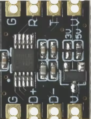
The pin configuration for a generic serial converter module is as follows:
| Pin Name | Description |
|---|---|
| VCC | Power input (3.3V or 5V, depending on the module) |
| GND | Ground connection |
| TXD | Transmit data (serial output) |
| RXD | Receive data (serial input) |
| RTS | Request to send (optional, for flow control) |
| CTS | Clear to send (optional, for flow control) |
| DTR | Data terminal ready (optional) |
| DSR | Data set ready (optional) |
Usage Instructions
How to Use the Component in a Circuit
- Power the Module: Connect the VCC pin to a 3.3V or 5V power source, depending on the module's specifications. Connect the GND pin to the ground of your circuit.
- Connect Data Lines:
- For serial communication, connect the TXD pin of the serial converter to the RXD pin of the target device, and the RXD pin of the serial converter to the TXD pin of the target device.
- If flow control is required, connect the RTS and CTS pins as needed.
- Interface with a Microcontroller: Use the serial converter to bridge communication between a microcontroller (e.g., Arduino) and a computer or another device.
- Install Drivers (if applicable): For USB-based serial converters, install the necessary drivers on your computer to enable communication.
Important Considerations and Best Practices
- Voltage Compatibility: Ensure the voltage levels of the serial converter match the target device to avoid damage.
- Signal Integrity: Use short, shielded cables for high-speed data transmission to minimize noise and signal degradation.
- Driver Installation: For USB-based converters, verify that the correct drivers are installed on your operating system.
- Baud Rate Matching: Ensure the baud rate of the serial converter matches the baud rate of the connected device.
Example: Connecting to an Arduino UNO
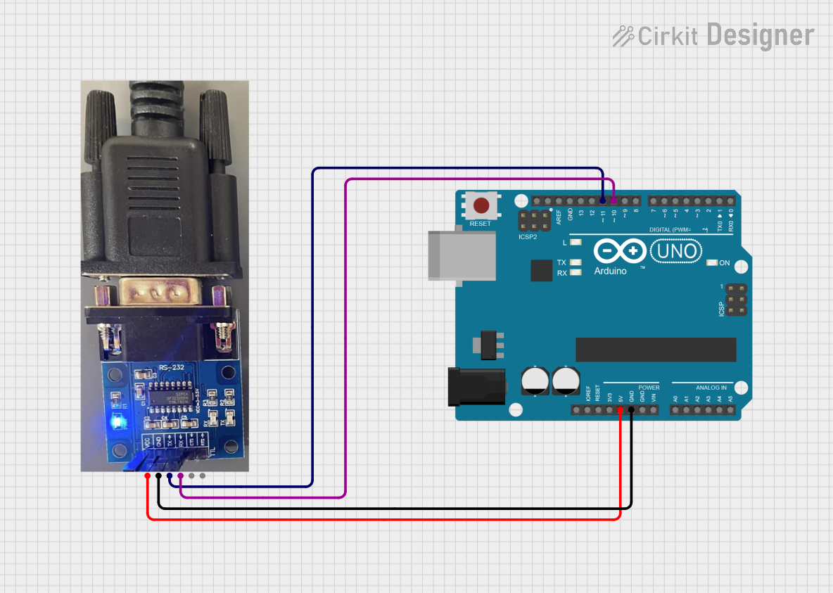
Below is an example of how to use a serial converter to communicate with an Arduino UNO.
Circuit Diagram
- Connect the serial converter's TXD pin to the Arduino's RX (pin 0).
- Connect the serial converter's RXD pin to the Arduino's TX (pin 1).
- Connect the GND pin of the serial converter to the Arduino's GND.
Arduino Code
// Example code to send and receive data using a serial converter
void setup() {
  Serial.begin(9600); // Initialize serial communication at 9600 baud
  Serial.println("Serial Converter Test"); // Send a test message
}

void loop() {
  if (Serial.available() > 0) {
    // Read incoming data from the serial converter
    char receivedData = Serial.read();
    // Echo the received data back to the sender
    Serial.print("Received: ");
    Serial.println(receivedData);
  }
}
Troubleshooting and FAQs
Common Issues and Solutions
No Data Transmission:
- Cause: Incorrect wiring or mismatched TXD/RXD connections.
- Solution: Verify that TXD is connected to RXD and vice versa.
Device Not Recognized (USB Converters):
- Cause: Missing or incorrect drivers.
- Solution: Install the correct drivers for your operating system. Check the manufacturer's website for driver downloads.
Data Corruption:
- Cause: Mismatched baud rates or noisy connections.
- Solution: Ensure the baud rate is the same on both devices. Use shielded cables for long connections.
Flow Control Issues:
- Cause: RTS/CTS or DTR/DSR not properly connected.
- Solution: Verify the flow control settings and connections.
FAQs
Q: Can I use a serial converter with a 3.3V device?
- A: Yes, but ensure the serial converter supports 3.3V operation or use a level shifter.
Q: What is the maximum cable length for a serial converter?
- A: For RS-232, the maximum recommended length is 15 meters. For USB, it is 5 meters without a repeater.
Q: Do I need to install drivers for all serial converters?
- A: USB-based converters typically require drivers, while UART-based converters do not.
Q: Can I use a serial converter for SPI or I2C communication?
- A: No, serial converters are designed for UART or RS-232 communication. Use protocol-specific converters for SPI or I2C.
This documentation provides a comprehensive guide to understanding, using, and troubleshooting a serial converter. For further assistance, consult the datasheet or contact the manufacturer.