Cirkit Designer Logo
Cirkit Designer
Your all-in-one circuit design IDE
Home / 
Component Documentation

How to Use ESP32-C3 Mini With DEV Board: Examples, Pinouts, and Specs

Image of ESP32-C3 Mini With DEV Board
Cirkit Designer LogoDesign with ESP32-C3 Mini With DEV Board in Cirkit Designer

Introduction

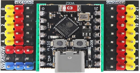
The ESP32-C3 Mini With DEV Board is a compact development board based on the ESP32-C3 chip. It features integrated Wi-Fi and Bluetooth Low Energy (BLE) capabilities, making it an excellent choice for Internet of Things (IoT) applications, smart devices, and rapid prototyping. Its small form factor and low power consumption make it ideal for battery-powered projects and space-constrained designs.

Explore Projects Built with ESP32-C3 Mini With DEV Board

Use Cirkit Designer to design, explore, and prototype these projects online. Some projects support real-time simulation. Click "Open Project" to start designing instantly!
ESP32-C3 and Micro SD Card Module for Data Logging
Image of Esp 32 super mini with MicroSd module: A project utilizing ESP32-C3 Mini With DEV Board in a practical application
This circuit features an ESP32-C3 microcontroller interfaced with a Micro SD Card Module. The ESP32-C3 handles SPI communication with the SD card for data storage and retrieval, with specific GPIO pins assigned for MOSI, MISO, SCK, and CS signals.
Cirkit Designer LogoOpen Project in Cirkit Designer
ESP32-Based GPS Tracker with SD Card Logging and Barometric Sensor
Image of gps projekt circuit: A project utilizing ESP32-C3 Mini With DEV Board in a practical application
This circuit features an ESP32 Wroom Dev Kit as the main microcontroller, interfaced with an MPL3115A2 sensor for pressure and temperature readings, and a Neo 6M GPS module for location tracking. The ESP32 is also connected to an SD card reader for data logging purposes. A voltage regulator is used to step down the USB power supply to 3.3V, which powers the ESP32, the sensor, and the SD card reader.
Cirkit Designer LogoOpen Project in Cirkit Designer
ESP32C3 and LoRa-Enabled Environmental Sensing Node
Image of temperature_KA: A project utilizing ESP32-C3 Mini With DEV Board in a practical application
This circuit features an ESP32C3 Supermini microcontroller connected to a LORA_RA02 module and a DHT11 temperature and humidity sensor. The ESP32C3 handles communication with the LORA module via SPI (using GPIO05, GPIO06, GPIO10, and GPIO04 for MISO, MOSI, NSS, and SCK respectively) and GPIO01 and GPIO02 for additional control signals. The DHT11 sensor is interfaced through GPIO03 for data reading, and all components share a common power supply through the 3.3V and GND pins.
Cirkit Designer LogoOpen Project in Cirkit Designer
ESP32-S3 GPS and Wind Speed Logger with Dual OLED Displays and CAN Bus
Image of esp32-s3-ellipse: A project utilizing ESP32-C3 Mini With DEV Board in a practical application
This circuit features an ESP32-S3 microcontroller interfaced with an SD card module, two OLED displays, a GPS module, and a CAN bus module. The ESP32-S3 records GPS data to the SD card, displays speed on one OLED, and shows wind speed from the CAN bus on the other OLED, providing a comprehensive data logging and display system.
Cirkit Designer LogoOpen Project in Cirkit Designer

Explore Projects Built with ESP32-C3 Mini With DEV Board

Use Cirkit Designer to design, explore, and prototype these projects online. Some projects support real-time simulation. Click "Open Project" to start designing instantly!
Image of Esp 32 super mini with MicroSd module: A project utilizing ESP32-C3 Mini With DEV Board in a practical application
ESP32-C3 and Micro SD Card Module for Data Logging
This circuit features an ESP32-C3 microcontroller interfaced with a Micro SD Card Module. The ESP32-C3 handles SPI communication with the SD card for data storage and retrieval, with specific GPIO pins assigned for MOSI, MISO, SCK, and CS signals.
Cirkit Designer LogoOpen Project in Cirkit Designer
Image of gps projekt circuit: A project utilizing ESP32-C3 Mini With DEV Board in a practical application
ESP32-Based GPS Tracker with SD Card Logging and Barometric Sensor
This circuit features an ESP32 Wroom Dev Kit as the main microcontroller, interfaced with an MPL3115A2 sensor for pressure and temperature readings, and a Neo 6M GPS module for location tracking. The ESP32 is also connected to an SD card reader for data logging purposes. A voltage regulator is used to step down the USB power supply to 3.3V, which powers the ESP32, the sensor, and the SD card reader.
Cirkit Designer LogoOpen Project in Cirkit Designer
Image of temperature_KA: A project utilizing ESP32-C3 Mini With DEV Board in a practical application
ESP32C3 and LoRa-Enabled Environmental Sensing Node
This circuit features an ESP32C3 Supermini microcontroller connected to a LORA_RA02 module and a DHT11 temperature and humidity sensor. The ESP32C3 handles communication with the LORA module via SPI (using GPIO05, GPIO06, GPIO10, and GPIO04 for MISO, MOSI, NSS, and SCK respectively) and GPIO01 and GPIO02 for additional control signals. The DHT11 sensor is interfaced through GPIO03 for data reading, and all components share a common power supply through the 3.3V and GND pins.
Cirkit Designer LogoOpen Project in Cirkit Designer
Image of esp32-s3-ellipse: A project utilizing ESP32-C3 Mini With DEV Board in a practical application
ESP32-S3 GPS and Wind Speed Logger with Dual OLED Displays and CAN Bus
This circuit features an ESP32-S3 microcontroller interfaced with an SD card module, two OLED displays, a GPS module, and a CAN bus module. The ESP32-S3 records GPS data to the SD card, displays speed on one OLED, and shows wind speed from the CAN bus on the other OLED, providing a comprehensive data logging and display system.
Cirkit Designer LogoOpen Project in Cirkit Designer

Common Applications and Use Cases

  • IoT devices and smart home automation
  • Wearable technology
  • Wireless sensor networks
  • Prototyping for Wi-Fi and BLE-enabled devices
  • Low-power, battery-operated systems

Technical Specifications

The ESP32-C3 Mini With DEV Board is designed to provide robust performance while maintaining a compact size. Below are its key technical specifications:

Key Technical Details

Parameter Specification
Microcontroller ESP32-C3 (RISC-V single-core @ 160 MHz)
Flash Memory 4 MB (onboard)
RAM 400 KB SRAM
Wireless Connectivity Wi-Fi 802.11 b/g/n (2.4 GHz), BLE 5.0
Operating Voltage 3.3V
Input Voltage (via USB) 5V
GPIO Pins 22
Communication Interfaces UART, SPI, I2C, I2S, PWM
ADC Channels 6 (12-bit resolution)
Power Consumption Ultra-low power (deep sleep: ~5 µA)
Dimensions 18 mm x 51 mm

Pin Configuration and Descriptions

The ESP32-C3 Mini With DEV Board features a standard pinout for easy integration into projects. Below is the pin configuration:

Pin Number Pin Name Function
1 3V3 3.3V Power Output
2 GND Ground
3 GPIO0 General Purpose I/O, Boot Mode Select
4 GPIO1 General Purpose I/O, UART TX
5 GPIO2 General Purpose I/O, UART RX
6 GPIO3 General Purpose I/O, ADC Input
7 GPIO4 General Purpose I/O, PWM Output
8 GPIO5 General Purpose I/O, SPI MOSI
9 GPIO6 General Purpose I/O, SPI MISO
10 GPIO7 General Purpose I/O, SPI CLK
11 EN Enable Pin (Active High)
12 RST Reset Pin

Usage Instructions

The ESP32-C3 Mini With DEV Board is easy to use and can be programmed using the Arduino IDE or ESP-IDF (Espressif IoT Development Framework). Below are the steps to get started:

How to Use the Component in a Circuit

  1. Powering the Board:

    • Connect the board to your computer or a USB power source using a micro-USB cable.
    • Ensure the input voltage is 5V via USB or 3.3V via the 3V3 pin.
  2. Connecting Peripherals:

    • Use the GPIO pins to connect sensors, actuators, or other peripherals.
    • Ensure the peripherals operate at 3.3V logic levels to avoid damaging the board.
  3. Programming the Board:

    • Install the necessary drivers for the ESP32-C3 on your computer.
    • Use the Arduino IDE or ESP-IDF to write and upload code to the board.

Important Considerations and Best Practices

  • Voltage Levels: The GPIO pins operate at 3.3V. Avoid applying 5V to any GPIO pin.
  • Boot Mode: To enter boot mode for flashing firmware, hold the GPIO0 pin low during reset.
  • Power Consumption: Use deep sleep mode to minimize power consumption in battery-powered applications.
  • Antenna Placement: Ensure the onboard antenna is not obstructed by metal objects to maintain optimal wireless performance.

Example Code for Arduino IDE

Below is an example code to blink an LED connected to GPIO4:

// Define the GPIO pin for the LED
#define LED_PIN 4

void setup() {
  // Initialize the LED pin as an output
  pinMode(LED_PIN, OUTPUT);
}

void loop() {
  // Turn the LED on
  digitalWrite(LED_PIN, HIGH);
  delay(1000); // Wait for 1 second

  // Turn the LED off
  digitalWrite(LED_PIN, LOW);
  delay(1000); // Wait for 1 second
}

Troubleshooting and FAQs

Common Issues Users Might Face

  1. Board Not Detected by Computer:

    • Ensure the USB cable is functional and supports data transfer.
    • Install the correct USB-to-serial drivers for the ESP32-C3.
  2. Code Upload Fails:

    • Check that the board is in boot mode (hold GPIO0 low during reset).
    • Verify the correct board and port are selected in the Arduino IDE.
  3. Wi-Fi Connection Issues:

    • Ensure the Wi-Fi credentials in your code are correct.
    • Check for interference or weak signal strength near the board.
  4. Overheating:

    • Avoid overloading the GPIO pins with excessive current.
    • Ensure proper ventilation around the board.

Solutions and Tips for Troubleshooting

  • Reset the Board: Press the RST button to reset the board if it becomes unresponsive.
  • Check Power Supply: Ensure the board is receiving a stable 5V input via USB or 3.3V via the 3V3 pin.
  • Update Firmware: Use the latest ESP32-C3 firmware to ensure compatibility and performance.
  • Debugging: Use the serial monitor in the Arduino IDE to debug and view error messages.

By following this documentation, you can effectively integrate the ESP32-C3 Mini With DEV Board into your projects and troubleshoot common issues.