How to Use 3s Bms with balancer 11.1v-12.6v: Examples, Pinouts, and Specs
Introduction
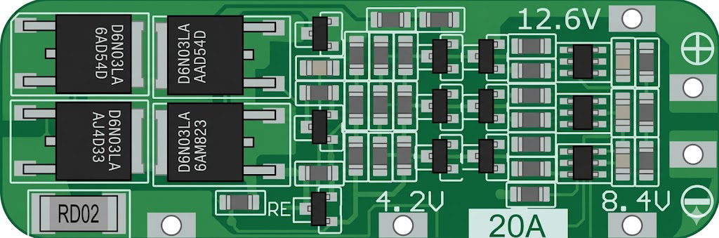
The 3S BMS with Balancer is a Battery Management System designed specifically for 3-cell lithium-ion battery packs. It operates within a voltage range of 11.1V to 12.6V and provides essential safety features such as overvoltage, undervoltage, overcurrent, and short-circuit protection. Additionally, it includes a balancing function to ensure that all cells in the battery pack maintain equal charge levels, thereby improving battery performance and lifespan.
Explore Projects Built with 3s Bms with balancer 11.1v-12.6v


Explore Projects Built with 3s Bms with balancer 11.1v-12.6v
Common Applications
- Lithium-ion battery packs for portable electronics
- Electric bicycles and scooters
- Solar energy storage systems
- Uninterruptible Power Supplies (UPS)
- DIY battery-powered projects
Technical Specifications
The following table outlines the key technical specifications of the 3S BMS with Balancer:
| Parameter | Value |
|---|---|
| Battery Configuration | 3S (3 cells in series) |
| Operating Voltage Range | 11.1V - 12.6V |
| Overcharge Protection | 4.25V ± 0.05V per cell |
| Overdischarge Protection | 2.7V ± 0.1V per cell |
| Maximum Continuous Current | 20A |
| Balancing Current | 30mA |
| Short-Circuit Protection | Yes |
| Dimensions | ~45mm x 17mm x 3mm |
| Operating Temperature Range | -40°C to 85°C |
Pin Configuration and Descriptions
The 3S BMS typically has the following pin connections:
| Pin Name | Description |
|---|---|
| B- | Battery negative terminal (connect to the negative terminal of the battery pack) |
| B1 | Connection point for the positive terminal of the first cell |
| B2 | Connection point for the positive terminal of the second cell |
| B+ | Battery positive terminal (connect to the positive terminal of the battery pack) |
| P- | Power output negative terminal (connect to the load or charger negative) |
| P+ | Power output positive terminal (connect to the load or charger positive) |
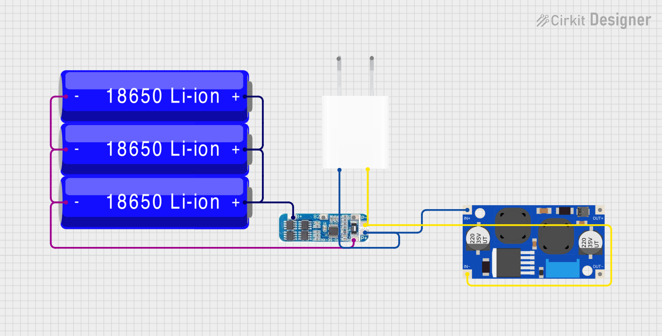
Usage Instructions
How to Use the 3S BMS in a Circuit
Connect the Battery Pack:
- Connect the negative terminal of the battery pack to the
B-pin. - Connect the positive terminal of the first cell to the
B1pin. - Connect the positive terminal of the second cell to the
B2pin. - Connect the positive terminal of the battery pack to the
B+pin.
- Connect the negative terminal of the battery pack to the
Connect the Load and Charger:
- Connect the negative terminal of the load or charger to the
P-pin. - Connect the positive terminal of the load or charger to the
P+pin.
- Connect the negative terminal of the load or charger to the
Verify Connections:
- Double-check all connections to ensure they are secure and correctly aligned with the pin configuration.
Power On:
- Once all connections are verified, the BMS will automatically manage the charging, discharging, and balancing of the battery pack.
Important Considerations
- Ensure that the battery pack consists of three lithium-ion cells connected in series.
- Do not exceed the maximum continuous current rating of 20A.
- Use a charger that is compatible with the voltage range of 11.1V to 12.6V.
- Avoid short-circuiting the terminals, as this may damage the BMS or the battery pack.
- Ensure proper heat dissipation if the BMS is used in high-current applications.
Arduino Integration Example
While the 3S BMS is primarily a hardware component, it can be monitored using an Arduino UNO to measure battery voltage and ensure proper operation. Below is an example code to read the voltage of the battery pack using an analog input pin:
// Arduino code to monitor the voltage of a 3S battery pack
const int voltagePin = A0; // Analog pin connected to the battery voltage divider
const float voltageDividerRatio = 5.7; // Adjust based on your resistor divider values
const float referenceVoltage = 5.0; // Reference voltage of the Arduino (5V for UNO)

void setup() {
  Serial.begin(9600); // Initialize serial communication
  pinMode(voltagePin, INPUT); // Set the voltage pin as input
}

void loop() {
  int rawValue = analogRead(voltagePin); // Read the analog value
  float batteryVoltage = (rawValue / 1023.0) * referenceVoltage * voltageDividerRatio;

  // Print the battery voltage to the Serial Monitor
  Serial.print("Battery Voltage: ");
  Serial.print(batteryVoltage);
  Serial.println(" V");

  delay(1000); // Wait for 1 second before the next reading
}
Note: Use a voltage divider circuit to step down the battery voltage to a safe range (0-5V) for the Arduino analog input pin. Adjust the
voltageDividerRatioin the code based on the resistor values used in the divider.
Troubleshooting and FAQs
Common Issues and Solutions
BMS Not Balancing Cells:
- Cause: The voltage difference between cells is too small.
- Solution: Ensure that the cells are at significantly different charge levels for the balancer to activate.
Overvoltage or Undervoltage Protection Triggered:
- Cause: The battery pack voltage is outside the operating range.
- Solution: Verify the voltage of each cell and ensure they are within the specified range (2.7V to 4.25V per cell).
No Output from P+ and P- Terminals:
- Cause: The BMS has entered protection mode due to a fault.
- Solution: Disconnect the load and charger, then reconnect the battery pack to reset the BMS.
Excessive Heat During Operation:
- Cause: High current draw or poor heat dissipation.
- Solution: Ensure the current does not exceed 20A and provide adequate ventilation.
FAQs
Can I use this BMS with a 4S battery pack?
- No, this BMS is specifically designed for 3-cell (3S) lithium-ion battery packs.
What happens if I reverse the polarity of the connections?
- Reversing the polarity may damage the BMS. Always double-check connections before powering on.
Does the BMS support lithium iron phosphate (LiFePO4) batteries?
- No, this BMS is designed for lithium-ion batteries with a nominal voltage of 3.7V per cell.
Can I use this BMS for charging and discharging simultaneously?
- Yes, the BMS is designed to handle both charging and discharging operations simultaneously.
By following this documentation, you can safely and effectively use the 3S BMS with Balancer in your projects.