How to Use C1001: Examples, Pinouts, and Specs

Introduction
The C1001 is a capacitor designed to store electrical energy in an electric field. It is commonly used in electronic circuits to smooth out voltage fluctuations, filter noise, and stabilize power supply lines. Capacitors like the C1001 are essential components in both analog and digital circuits, ensuring reliable operation and protecting sensitive components from voltage spikes.
Explore Projects Built with C1001

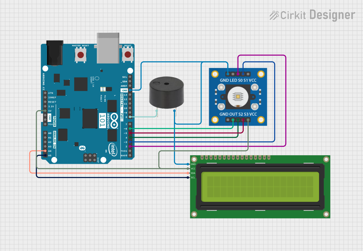
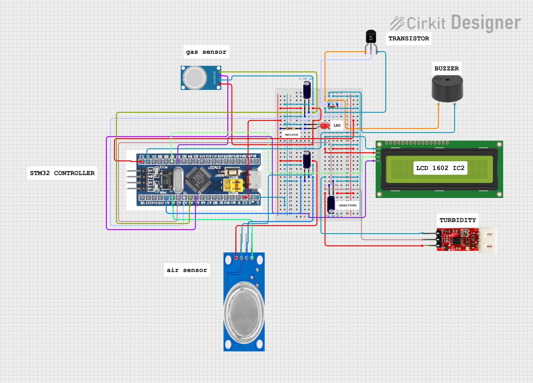

Explore Projects Built with C1001
Common Applications:
- Power supply filtering to reduce voltage ripple
- Decoupling in digital circuits to stabilize voltage levels
- Energy storage in timing and oscillator circuits
- Noise suppression in audio and RF circuits
Technical Specifications
The C1001 capacitor is a general-purpose component with the following key specifications:
| Parameter | Value |
|---|---|
| Capacitance | 100 µF |
| Voltage Rating | 25 V |
| Tolerance | ±20% |
| Type | Electrolytic |
| Operating Temperature | -40°C to +85°C |
| ESR (Equivalent Series Resistance) | 0.1 Ω (typical) |
Pin Configuration and Descriptions
The C1001 capacitor has two leads (pins) with the following configuration:
| Pin | Description |
|---|---|
| Positive (+) | Connected to the higher voltage side of the circuit. |
| Negative (-) | Connected to the lower voltage or ground. Marked with a stripe. |
Note: The negative pin is typically shorter and marked with a stripe on the capacitor body.
Usage Instructions
How to Use the C1001 in a Circuit
- Polarity Check: The C1001 is a polarized capacitor, meaning it must be connected with the correct polarity. The positive pin should be connected to the higher voltage, and the negative pin to the ground or lower voltage.
- Voltage Rating: Ensure the applied voltage does not exceed the capacitor's 25 V rating to avoid damage or failure.
- Placement: Place the capacitor as close as possible to the component or circuit section it is stabilizing to minimize inductance and resistance in the connections.
- Soldering: When soldering, avoid excessive heat to prevent damage to the capacitor.
Example: Using C1001 with an Arduino UNO
The C1001 can be used to stabilize the power supply for an Arduino UNO. Below is an example of connecting the capacitor to smooth out voltage fluctuations from a 5V power source.
Circuit Diagram:
- Connect the positive pin of the C1001 to the 5V pin of the Arduino.
- Connect the negative pin of the C1001 to the GND pin of the Arduino.
Code Example:
Although the capacitor itself does not require programming, here is an example of how it can be used in a circuit with an Arduino to stabilize a sensor reading:
// Example: Reading a sensor with stabilized power using the C1001 capacitor
const int sensorPin = A0; // Analog pin connected to the sensor
int sensorValue = 0;      // Variable to store the sensor reading

void setup() {
  Serial.begin(9600); // Initialize serial communication
}

void loop() {
  sensorValue = analogRead(sensorPin); // Read the sensor value
  Serial.println(sensorValue);        // Print the value to the Serial Monitor
  delay(500);                         // Wait for 500ms before the next reading
}
Note: The C1001 capacitor helps reduce noise in the sensor's power supply, leading to more stable readings.
Best Practices:
- Always verify the capacitor's polarity before connecting it to the circuit.
- Use capacitors with a voltage rating at least 1.5 times higher than the expected operating voltage for added safety.
- Avoid exposing the capacitor to temperatures beyond its operating range.
Troubleshooting and FAQs
Common Issues and Solutions:
Issue: The capacitor gets hot during operation.
- Solution: Check if the applied voltage exceeds the capacitor's 25 V rating. Replace the capacitor if it is damaged.
Issue: The circuit is not functioning as expected.
- Solution: Verify the polarity of the capacitor. Reversing the polarity can cause malfunction or damage.
Issue: The capacitor is physically swollen or leaking.
- Solution: Replace the capacitor immediately. This is a sign of failure due to overvoltage, overheating, or aging.
Issue: Noise or voltage fluctuations persist in the circuit.
- Solution: Ensure the capacitor is placed close to the component it is stabilizing. Check for loose connections or damaged traces.
FAQs:
Q: Can I use the C1001 in an AC circuit?
A: No, the C1001 is a polarized capacitor and is designed for DC circuits only. Using it in an AC circuit can cause damage.Q: What happens if I connect the capacitor with reversed polarity?
A: Reversing the polarity can cause the capacitor to overheat, leak, or even explode. Always double-check the polarity before connecting.Q: Can I use a higher capacitance value instead of the C1001?
A: Yes, but ensure the replacement capacitor has a similar or higher voltage rating and fits within the circuit's design requirements.
By following this documentation, you can effectively use the C1001 capacitor in your electronic projects and troubleshoot common issues with ease.