
How to Use Adafruit HX711 24-bit ADC: Examples, Pinouts, and Specs
 Design with Adafruit HX711 24-bit ADC in Cirkit Designer
Introduction
The Adafruit HX711 is a precision 24-bit analog-to-digital converter (ADC) designed for applications requiring high accuracy and low noise, such as weighing scales and industrial control systems. It features a built-in programmable gain amplifier (PGA) that simplifies the process of interfacing with load cells and other sensors. The HX711 is widely used in projects where precise measurement of small signals is critical.
Explore Projects Built with Adafruit HX711 24-bit ADC
 Open Project in Cirkit Designer
 Open Project in Cirkit Designer
 Open Project in Cirkit Designer
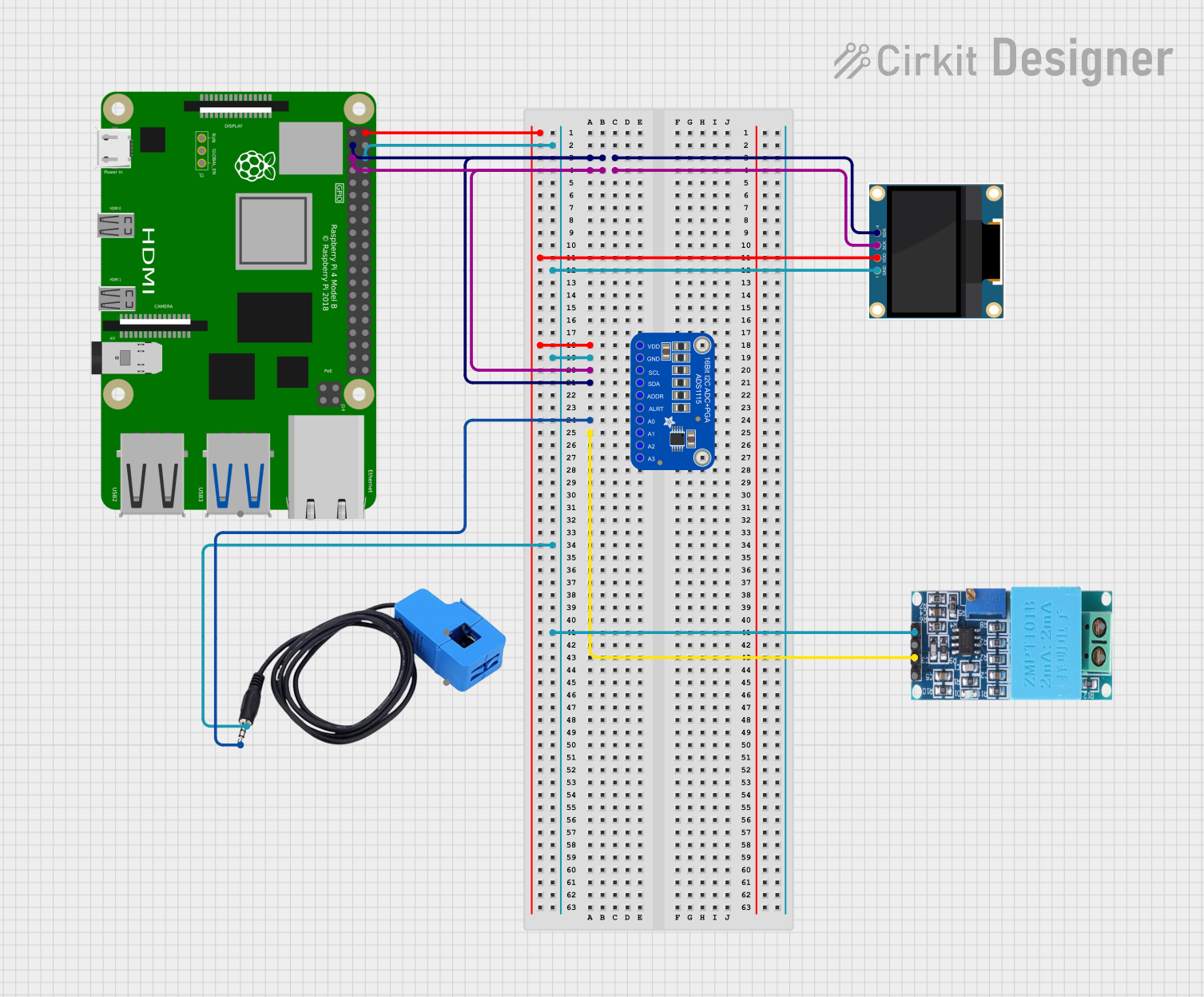 Open Project in Cirkit Designer
Explore Projects Built with Adafruit HX711 24-bit ADC
Open Project in Cirkit DesignerOpen Project in Cirkit DesignerOpen Project in Cirkit DesignerOpen Project in Cirkit DesignerCommon Applications and Use Cases
- Digital weighing scales
- Industrial process control
- Load cell interfacing
- Force and pressure measurement systems
- DIY electronics projects requiring high-resolution ADCs
Technical Specifications
The Adafruit HX711 is optimized for high-precision measurements and offers the following key specifications:
| Parameter | Value |
|---|---|
| ADC Resolution | 24-bit |
| Operating Voltage | 2.6V to 5.5V |
| Typical Operating Current | ~1.5mA |
| Standby Current | <1µA |
| Input Channels | 2 (Channel A and Channel B) |
| Programmable Gain | 32, 64, or 128 (Channel A only) |
| Data Rate | 10 Hz or 80 Hz |
| Interface | Serial (Clock and Data pins) |
| Temperature Range | -40°C to +85°C |
Pin Configuration and Descriptions
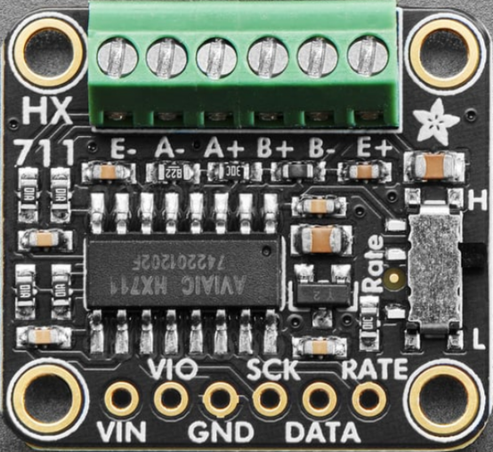
The HX711 module has a total of 4 pins for power and communication, along with 4 additional pins for sensor connections. Below is the pinout:
Power and Communication Pins
| Pin Name | Description |
|---|---|
| VCC | Power supply input (2.6V to 5.5V) |
| GND | Ground |
| DT (DATA) | Serial data output |
| SCK (CLOCK) | Serial clock input |
Sensor Connection Pins
| Pin Name | Description |
|---|---|
| E+ | Positive excitation voltage for the load cell |
| E- | Negative excitation voltage for the load cell |
| A+ | Positive signal input for Channel A |
| A- | Negative signal input for Channel A |
| B+ | Positive signal input for Channel B |
| B- | Negative signal input for Channel B |
Usage Instructions
How to Use the HX711 in a Circuit
- Power the Module: Connect the VCC pin to a 3.3V or 5V power source and the GND pin to ground.
- Connect the Load Cell: Attach the load cell wires to the E+, E-, A+, and A- pins. For single-channel use, Channel A is recommended due to its higher gain options.
- Connect to a Microcontroller: Use the DT and SCK pins to interface with a microcontroller, such as an Arduino UNO.
- Install Required Libraries: If using an Arduino, install the "HX711" library from the Arduino Library Manager for simplified communication.
- Write and Upload Code: Use the example code below to read data from the HX711.
Example Code for Arduino UNO
#include "HX711.h"

// Define HX711 pins
#define DT_PIN 3  // Data pin connected to Arduino digital pin 3
#define SCK_PIN 2 // Clock pin connected to Arduino digital pin 2

// Create an HX711 object
HX711 scale;

void setup() {
  Serial.begin(9600); // Initialize serial communication
  scale.begin(DT_PIN, SCK_PIN); // Initialize HX711 with defined pins
  Serial.println("HX711 initialized. Place weight on the scale.");
}

void loop() {
  if (scale.is_ready()) {
    // Read raw data from the HX711
    long reading = scale.get_units();
    Serial.print("Weight: ");
    Serial.print(reading);
    Serial.println(" units");
  } else {
    Serial.println("HX711 not ready. Check connections.");
  }
  delay(500); // Wait 500ms before the next reading
}
Important Considerations and Best Practices
- Power Supply: Ensure a stable power supply to minimize noise and improve measurement accuracy.
- Load Cell Wiring: Double-check the wiring of the load cell to avoid incorrect readings.
- Calibration: Always calibrate the HX711 with a known weight before use to ensure accurate measurements.
- Data Rate: Use the 10 Hz data rate for higher resolution or 80 Hz for faster readings.
- Shielding: Use shielded cables for the load cell to reduce electromagnetic interference.
Troubleshooting and FAQs
Common Issues and Solutions
No Data Output
- Cause: Loose or incorrect wiring.
- Solution: Verify all connections, especially the DT and SCK pins.
Inconsistent Readings
- Cause: Unstable power supply or noisy environment.
- Solution: Use a regulated power supply and shielded cables.
HX711 Not Ready
- Cause: Faulty module or incorrect initialization.
- Solution: Check the module's power supply and ensure the
scale.begin()function is called correctly.
Incorrect Weight Measurements
- Cause: Improper calibration or load cell wiring.
- Solution: Recalibrate the HX711 and verify the load cell connections.
FAQs
Q: Can I use the HX711 with a 3.3V microcontroller?
A: Yes, the HX711 operates with a voltage range of 2.6V to 5.5V, making it compatible with 3.3V systems.
Q: How do I change the gain setting?
A: The gain is set by the number of clock pulses sent to the SCK pin during initialization. The HX711 library handles this automatically.
Q: Can I use both channels (A and B) simultaneously?
A: Yes, but note that Channel A supports higher gain (32, 64, or 128), while Channel B has a fixed gain of 32.
Q: What is the maximum weight the HX711 can measure?
A: The maximum weight depends on the load cell used. The HX711 itself does not impose a weight limit but provides high-resolution readings for the connected load cell.