Cirkit Designer
Your all-in-one circuit design IDE
Home /
Component Documentation
How to Use Switch Symbol SPST: Examples, Pinouts, and Specs

Introduction
- A Single Pole Single Throw (SPST) switch is a basic on/off switch that controls a single circuit. It has two terminals and can either connect or disconnect the circuit, allowing or interrupting the flow of current.
- Common applications include simple on/off control for devices, power switches, and circuit isolation in low-voltage and low-current applications.
Explore Projects Built with Switch Symbol SPST
9V Battery-Powered DC Motor with Toggle Switch Control
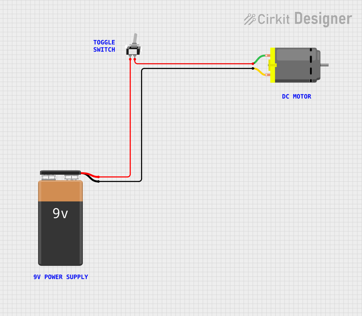
This circuit is designed to control a DC motor using a single-pole single-throw (SPST) toggle switch. The 9V battery provides power to the motor, and the toggle switch acts as an on/off control to allow or interrupt the current flow to the motor.
SPST Rocker Switch Array Circuit

This circuit features a parallel arrangement of SPST rocker switches, each capable of independently controlling the connection of a separate circuit branch to a common line. It is likely designed for simple on/off control of multiple individual loads or signals, with each switch operating a distinct load or signal path.
Battery-Powered 4-Channel Relay Control with LED Indicators

This circuit consists of a 5V battery powering a 4-channel relay module, which controls four LEDs (red, yellow, green, and blue) through individual resistors. Each relay channel is activated by a corresponding SPST toggle switch, allowing manual control of the LEDs.
Battery-Powered DC Motor Control with Rocker Switch
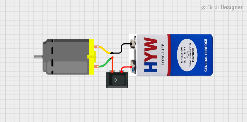
This circuit controls a DC motor using a 9V battery and a single-pole single-throw (SPST) rocker switch. The switch allows the user to turn the motor on and off by connecting or disconnecting the power from the battery to the motor.
Explore Projects Built with Switch Symbol SPST
9V Battery-Powered DC Motor with Toggle Switch Control
This circuit is designed to control a DC motor using a single-pole single-throw (SPST) toggle switch. The 9V battery provides power to the motor, and the toggle switch acts as an on/off control to allow or interrupt the current flow to the motor.
SPST Rocker Switch Array Circuit
This circuit features a parallel arrangement of SPST rocker switches, each capable of independently controlling the connection of a separate circuit branch to a common line. It is likely designed for simple on/off control of multiple individual loads or signals, with each switch operating a distinct load or signal path.
Battery-Powered 4-Channel Relay Control with LED Indicators
This circuit consists of a 5V battery powering a 4-channel relay module, which controls four LEDs (red, yellow, green, and blue) through individual resistors. Each relay channel is activated by a corresponding SPST toggle switch, allowing manual control of the LEDs.
Battery-Powered DC Motor Control with Rocker Switch
This circuit controls a DC motor using a 9V battery and a single-pole single-throw (SPST) rocker switch. The switch allows the user to turn the motor on and off by connecting or disconnecting the power from the battery to the motor.
Technical Specifications
- Type: Single Pole Single Throw (SPST)
- Number of Terminals: 2
- Voltage Rating: Typically ranges from 3V to 250V (depending on the specific model)
- Current Rating: Typically ranges from 0.5A to 15A (depending on the specific model)
- Contact Resistance: < 50 mΩ (typical)
- Insulation Resistance: > 100 MΩ at 500V DC
- Mechanical Life: 10,000 to 100,000 cycles (varies by model)
Pin Configuration and Descriptions
| Pin Number | Name | Description |
|---|---|---|
| 1 | Terminal 1 | Connects to one side of the circuit |
| 2 | Terminal 2 | Connects to the other side of the circuit |
Usage Instructions
Connecting the SPST Switch in a Circuit:
- Identify the two terminals of the SPST switch.
- Connect one terminal to the power source or input signal.
- Connect the other terminal to the load or output signal.
- When the switch is in the "ON" position, the circuit is closed, allowing current to flow. In the "OFF" position, the circuit is open, interrupting the current flow.
Important Considerations:
- Ensure the voltage and current ratings of the switch match the requirements of your circuit.
- Avoid exceeding the switch's ratings to prevent damage or failure.
- For AC circuits, ensure proper insulation and safety measures are in place.
- For DC circuits, be mindful of potential arcing when switching high currents.
Using an SPST Switch with an Arduino UNO:
- The SPST switch can be used as a digital input to control an Arduino program. Below is an example circuit and code:
- Connect one terminal of the switch to a digital input pin on the Arduino (e.g., pin 2).
- Connect the other terminal to ground.
- Use a pull-up resistor (internal or external) to ensure a stable input signal.
- The SPST switch can be used as a digital input to control an Arduino program. Below is an example circuit and code:
// Example code for using an SPST switch with Arduino UNO
const int switchPin = 2;  // Pin connected to the SPST switch
const int ledPin = 13;    // Pin connected to the onboard LED

void setup() {
  pinMode(switchPin, INPUT_PULLUP); // Enable internal pull-up resistor
  pinMode(ledPin, OUTPUT);          // Set LED pin as output
}

void loop() {
  int switchState = digitalRead(switchPin); // Read the state of the switch

  if (switchState == LOW) { // Switch is pressed (connected to ground)
    digitalWrite(ledPin, HIGH); // Turn on the LED
  } else { // Switch is not pressed
    digitalWrite(ledPin, LOW);  // Turn off the LED
  }
}
Troubleshooting and FAQs
Common Issues
Switch does not work or fails to control the circuit:
- Solution: Verify the connections. Ensure the switch terminals are properly connected to the circuit.
- Solution: Check if the switch is damaged or worn out. Replace if necessary.
Switch generates sparks or arcs when toggled:
- Solution: Ensure the switch's voltage and current ratings are not being exceeded.
- Solution: For high-current applications, consider using a relay or a switch with higher ratings.
Arduino does not detect the switch state correctly:
- Solution: Ensure the pull-up resistor is enabled (internal or external).
- Solution: Check for loose connections or faulty wiring.
FAQs
Can I use an SPST switch for AC circuits?
- Yes, as long as the switch's voltage and current ratings are suitable for the AC circuit.
What is the difference between SPST and SPDT switches?
- An SPST switch has two terminals and controls a single circuit. An SPDT (Single Pole Double Throw) switch has three terminals and can toggle between two circuits.
How do I test if an SPST switch is working?
- Use a multimeter in continuity mode. When the switch is "ON," the multimeter should beep, indicating continuity. When "OFF," there should be no continuity.