How to Use Wireless Motor Controller: Examples, Pinouts, and Specs
Introduction
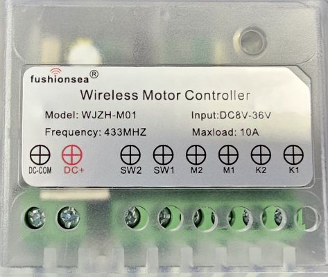
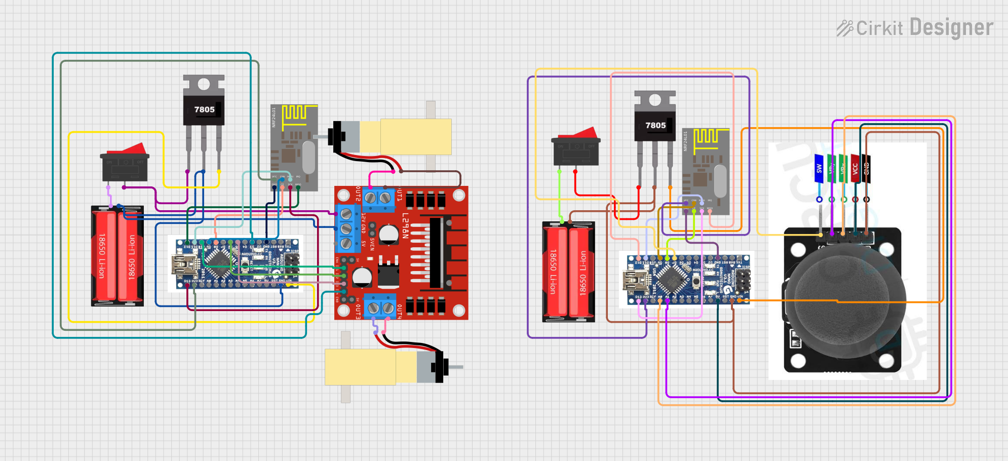
A Wireless Motor Controller is an electronic device designed to remotely control the operation of motors. It integrates wireless communication capabilities with motor driver circuitry, enabling users to start, stop, and regulate the speed and direction of a motor from a distance. This component is commonly used in applications such as remote-controlled vehicles, home automation systems, industrial machinery, and robotics.
Explore Projects Built with Wireless Motor Controller
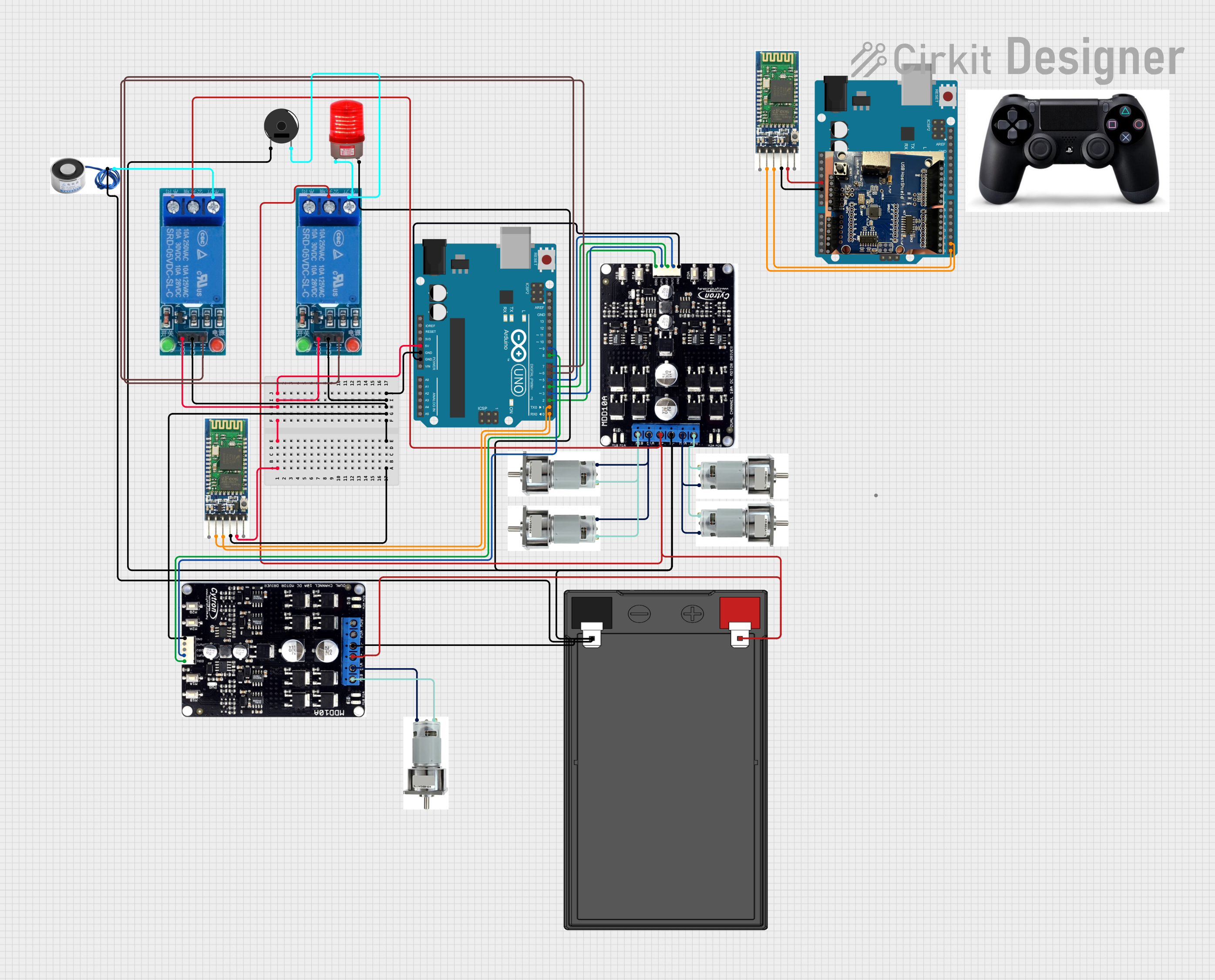
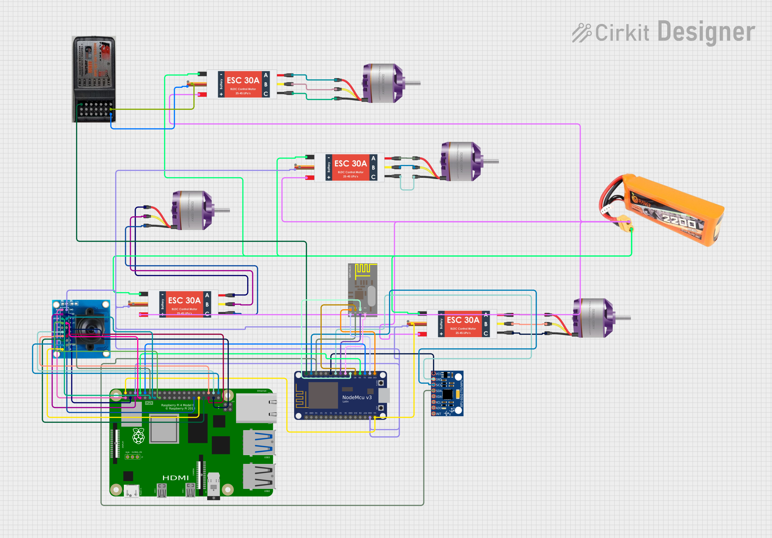
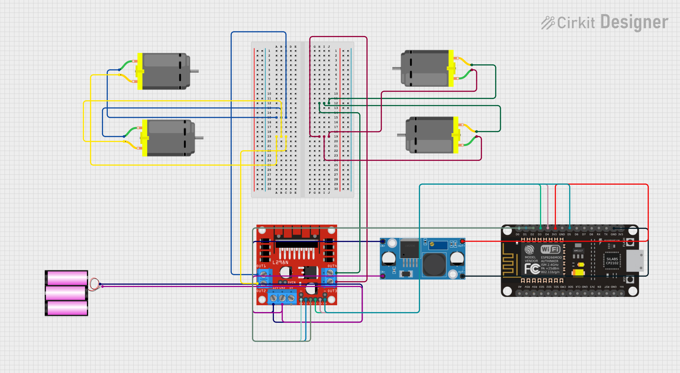
Explore Projects Built with Wireless Motor Controller
Technical Specifications
General Specifications
- Operating Voltage: 6V to 12V DC
- Continuous Current Rating: 2A per channel
- Peak Current: 3A per channel
- Communication Frequency: 2.4 GHz
- Communication Protocol: Bluetooth/Wi-Fi (specify as per the model)
- Control Channels: 2 (for bidirectional control of one motor or control of two motors)
- Operating Temperature: -25°C to +85°C
Pin Configuration and Descriptions
| Pin Number | Pin Name | Description |
|---|---|---|
| 1 | VCC | Power supply input (6V-12V DC) |
| 2 | GND | Ground connection |
| 3 | IN1 | Input signal for motor channel 1 |
| 4 | IN2 | Input signal for motor channel 2 |
| 5 | OUT1 | Output to motor channel 1 |
| 6 | OUT2 | Output to motor channel 2 |
| 7 | RX | Receiver pin for wireless communication |
| 8 | TX | Transmitter pin for wireless communication |
Usage Instructions
Connecting the Wireless Motor Controller
- Connect the motor's leads to the OUT1 and OUT2 terminals.
- Supply power to the VCC and GND pins, ensuring the voltage is within the specified range.
- Establish a connection between the RX and TX pins and the wireless communication module.
Controlling the Motor
- To control the motor, send appropriate commands from your wireless transmitter to the Wireless Motor Controller.
- Use the IN1 and IN2 pins to set the direction of the motor. For example, setting IN1 to HIGH and IN2 to LOW will rotate the motor in one direction, while reversing these signals will rotate the motor in the opposite direction.
- Implement pulse-width modulation (PWM) on the input pins to control the speed of the motor.
Best Practices
- Always ensure that the power supply voltage and current do not exceed the controller's ratings.
- Use a proper heat sink if operating the controller near its maximum current rating.
- Ensure that the wireless communication protocol and frequency match between the controller and the transmitter.
- Protect the controller from environmental factors such as moisture and dust.
Example Code for Arduino UNO
#include <SoftwareSerial.h>

SoftwareSerial mySerial(10, 11); // RX, TX

const int motorPin1 = 3; // IN1 on the motor controller
const int motorPin2 = 4; // IN2 on the motor controller

void setup() {
  pinMode(motorPin1, OUTPUT);
  pinMode(motorPin2, OUTPUT);
  mySerial.begin(9600); // Set the baud rate to match the controller
}

void loop() {
  if (mySerial.available()) {
    char command = mySerial.read();
    switch (command) {
      case 'f': // Forward command
        digitalWrite(motorPin1, HIGH);
        digitalWrite(motorPin2, LOW);
        break;
      case 'r': // Reverse command
        digitalWrite(motorPin1, LOW);
        digitalWrite(motorPin2, HIGH);
        break;
      case 's': // Stop command
        digitalWrite(motorPin1, LOW);
        digitalWrite(motorPin2, LOW);
        break;
      // Add more cases as needed for speed control
    }
  }
}
Troubleshooting and FAQs
Common Issues
- Motor not responding: Ensure all connections are secure and the power supply is within the specified range.
- Intermittent operation: Check for loose connections or signal interference.
- Overheating: Make sure the current draw is within limits and use a heat sink if necessary.
FAQs
Q: Can I control more than one motor? A: Yes, the controller has two channels, allowing for the control of two motors or bidirectional control of one motor.
Q: What wireless protocols can be used with this controller? A: It depends on the model. Common protocols include Bluetooth and Wi-Fi.
Q: How can I adjust the speed of the motor? A: Use PWM on the input pins to control the speed. The duty cycle of the PWM signal will determine the motor speed.
Q: Is it possible to control the motor from a smartphone? A: Yes, if the wireless module supports Bluetooth or Wi-Fi, you can use a smartphone app to send control commands.
For further assistance, consult the manufacturer's datasheet or contact technical support.