How to Use CB2S WiFi Board: Examples, Pinouts, and Specs
Introduction
The CB2S WiFi Board is a compact and versatile development board designed for Internet of Things (IoT) applications. It features built-in WiFi connectivity, making it ideal for wireless communication in smart devices and automation projects. With its GPIO pins, the CB2S board allows seamless interfacing with sensors, actuators, and other peripherals. It supports multiple programming environments, making it suitable for both beginners and experienced developers.
Explore Projects Built with CB2S WiFi Board


Explore Projects Built with CB2S WiFi Board
Common Applications and Use Cases
- Smart home automation (e.g., controlling lights, thermostats, or appliances)
- Wireless sensor networks
- IoT-enabled industrial monitoring and control
- Remote data logging and cloud integration
- Prototyping WiFi-enabled devices
Technical Specifications
The CB2S WiFi Board is built to deliver reliable performance in a compact form factor. Below are its key technical details:
Key Technical Details
| Parameter | Specification |
|---|---|
| Microcontroller | ESP8285 (ESP8266-based SoC with 1 MB Flash) |
| WiFi Standard | IEEE 802.11 b/g/n (2.4 GHz) |
| Operating Voltage | 3.3V |
| Input Voltage Range | 3.0V - 3.6V |
| GPIO Pins | 9 (configurable for digital I/O, PWM, etc.) |
| Communication Protocols | UART, SPI, I2C |
| Power Consumption | 15 mA (idle), up to 200 mA (transmit) |
| Dimensions | 18 mm x 20 mm |
| Operating Temperature | -40°C to +85°C |
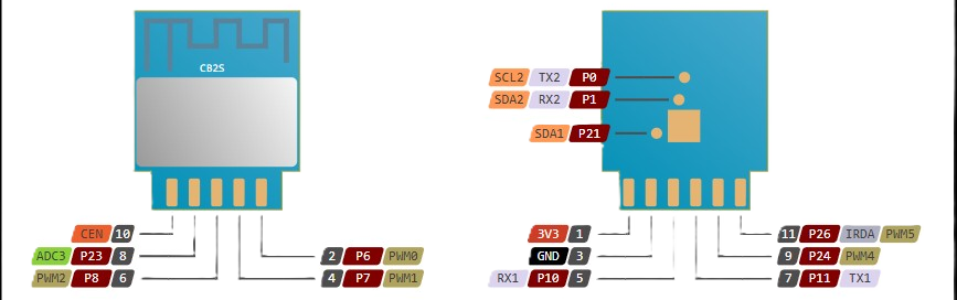
Pin Configuration and Descriptions
The CB2S WiFi Board has a total of 12 pins, including power, ground, and GPIO pins. Below is the pinout description:
| Pin Number | Pin Name | Description |
|---|---|---|
| 1 | VCC | Power input (3.3V) |
| 2 | GND | Ground |
| 3 | TXD | UART Transmit (for serial communication) |
| 4 | RXD | UART Receive (for serial communication) |
| 5 | GPIO0 | General-purpose I/O (can be used for PWM) |
| 6 | GPIO1 | General-purpose I/O |
| 7 | GPIO2 | General-purpose I/O |
| 8 | GPIO3 | General-purpose I/O |
| 9 | GPIO4 | General-purpose I/O |
| 10 | GPIO5 | General-purpose I/O |
| 11 | EN | Enable pin (active high) |
| 12 | RST | Reset pin (active low) |
Usage Instructions
How to Use the CB2S WiFi Board in a Circuit
- Powering the Board: Connect the VCC pin to a 3.3V power source and the GND pin to ground. Ensure the input voltage does not exceed 3.6V to avoid damaging the board.
- Programming the Board: Use a USB-to-UART adapter to connect the TXD and RXD pins to your computer. Popular programming environments include the Arduino IDE and ESP8266 SDK.
- Connecting Peripherals: Use the GPIO pins to interface with sensors, actuators, or other devices. Configure the pins as input or output in your code as needed.
- WiFi Configuration: Use the built-in WiFi module to connect to a local network. The board supports both station and access point modes.
Important Considerations and Best Practices
- Always use a 3.3V regulator if powering the board from a higher voltage source.
- Avoid leaving unused GPIO pins floating; connect them to ground or VCC through a pull-up or pull-down resistor.
- Use decoupling capacitors near the power pins to ensure stable operation.
- When programming, ensure GPIO0 is pulled low to enter flash mode.
Example Code for Arduino UNO
Below is an example of how to use the CB2S WiFi Board with the Arduino IDE to connect to a WiFi network and send data to a server:
#include <ESP8266WiFi.h> // Include the ESP8266 WiFi library

const char* ssid = "Your_SSID";       // Replace with your WiFi network name
const char* password = "Your_Password"; // Replace with your WiFi password
const char* server = "http://example.com"; // Replace with your server URL

void setup() {
  Serial.begin(115200); // Initialize serial communication at 115200 baud
  WiFi.begin(ssid, password); // Connect to WiFi network

  Serial.print("Connecting to WiFi");
  while (WiFi.status() != WL_CONNECTED) {
    delay(500);
    Serial.print("."); // Print dots while connecting
  }
  Serial.println("\nWiFi connected!");
  Serial.println("IP Address: ");
  Serial.println(WiFi.localIP()); // Print the assigned IP address
}

void loop() {
  if (WiFi.status() == WL_CONNECTED) {
    WiFiClient client; // Create a WiFi client object
    if (client.connect(server, 80)) { // Connect to the server on port 80
      client.println("GET / HTTP/1.1"); // Send an HTTP GET request
      client.println("Host: example.com");
      client.println("Connection: close");
      client.println();
    }
    client.stop(); // Close the connection
  }
  delay(10000); // Wait 10 seconds before sending the next request
}
Troubleshooting and FAQs
Common Issues and Solutions
The board does not power on:
- Ensure the input voltage is within the 3.0V to 3.6V range.
- Check the connections to the VCC and GND pins.
Unable to upload code:
- Verify that GPIO0 is pulled low during programming.
- Check the TXD and RXD connections to the USB-to-UART adapter.
- Ensure the correct COM port and board settings are selected in the Arduino IDE.
WiFi connection fails:
- Double-check the SSID and password in your code.
- Ensure the WiFi network is within range and supports 2.4 GHz.
Unstable operation or frequent resets:
- Add decoupling capacitors (e.g., 0.1 µF and 10 µF) near the power pins.
- Verify that the power supply can provide sufficient current (at least 300 mA).
FAQs
Can the CB2S board operate on 5V? No, the CB2S board is designed to operate at 3.3V. Using 5V may damage the board.
What programming environments are supported? The CB2S board supports the Arduino IDE, ESP8266 SDK, and other environments compatible with the ESP8285.
How many devices can the CB2S connect to in access point mode? The CB2S board can support up to 4 devices in access point mode.
Can I use the CB2S for battery-powered applications? Yes, the CB2S is suitable for battery-powered applications due to its low power consumption. Use a 3.3V regulator for stable operation.