How to Use PMS5003 Board: Examples, Pinouts, and Specs
Introduction
The PMS5003 Board is a compact and highly accurate air quality sensor designed to measure particulate matter (PM1.0, PM2.5, and PM10) concentrations in the air. It employs advanced laser scattering technology to detect and quantify airborne particles, making it an essential tool for environmental monitoring, air purifiers, HVAC systems, and indoor air quality assessments.
This sensor is widely used in applications such as:
- Smart home air quality monitoring systems
- Industrial and environmental pollution monitoring
- Air purifiers and HVAC systems
- Research and development in air quality studies
Explore Projects Built with PMS5003 Board

Explore Projects Built with PMS5003 Board
Technical Specifications
The PMS5003 Board is designed for precision and reliability. Below are its key technical details:
General Specifications
| Parameter | Value |
|---|---|
| Operating Voltage | 4.5V to 5.5V |
| Operating Current | ≤ 100mA |
| Particle Size Detection | 0.3µm to 10µm |
| Measurement Range | 0 to 1,000 µg/m³ |
| Output Interface | UART (3.3V logic level) |
| Response Time | ≤ 1 second |
| Operating Temperature | -10°C to 60°C |
| Operating Humidity | 0% to 99% RH (non-condensing) |
| Dimensions | 50mm x 38mm x 21mm |
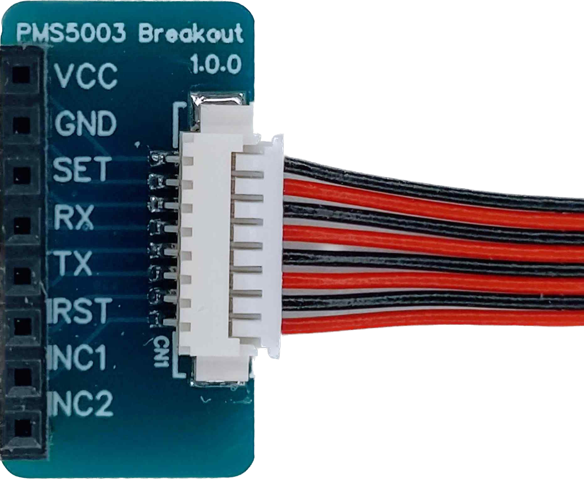
Pin Configuration
The PMS5003 Board has a 7-pin connector for interfacing. Below is the pinout description:
| Pin Number | Pin Name | Description |
|---|---|---|
| 1 | VCC | Power supply input (4.5V to 5.5V) |
| 2 | GND | Ground |
| 3 | SET | Standby control pin (active low) |
| 4 | RX | UART receive pin (3.3V logic level) |
| 5 | TX | UART transmit pin (3.3V logic level) |
| 6 | RESET | Reset pin (active low) |
| 7 | NC | Not connected |
Usage Instructions
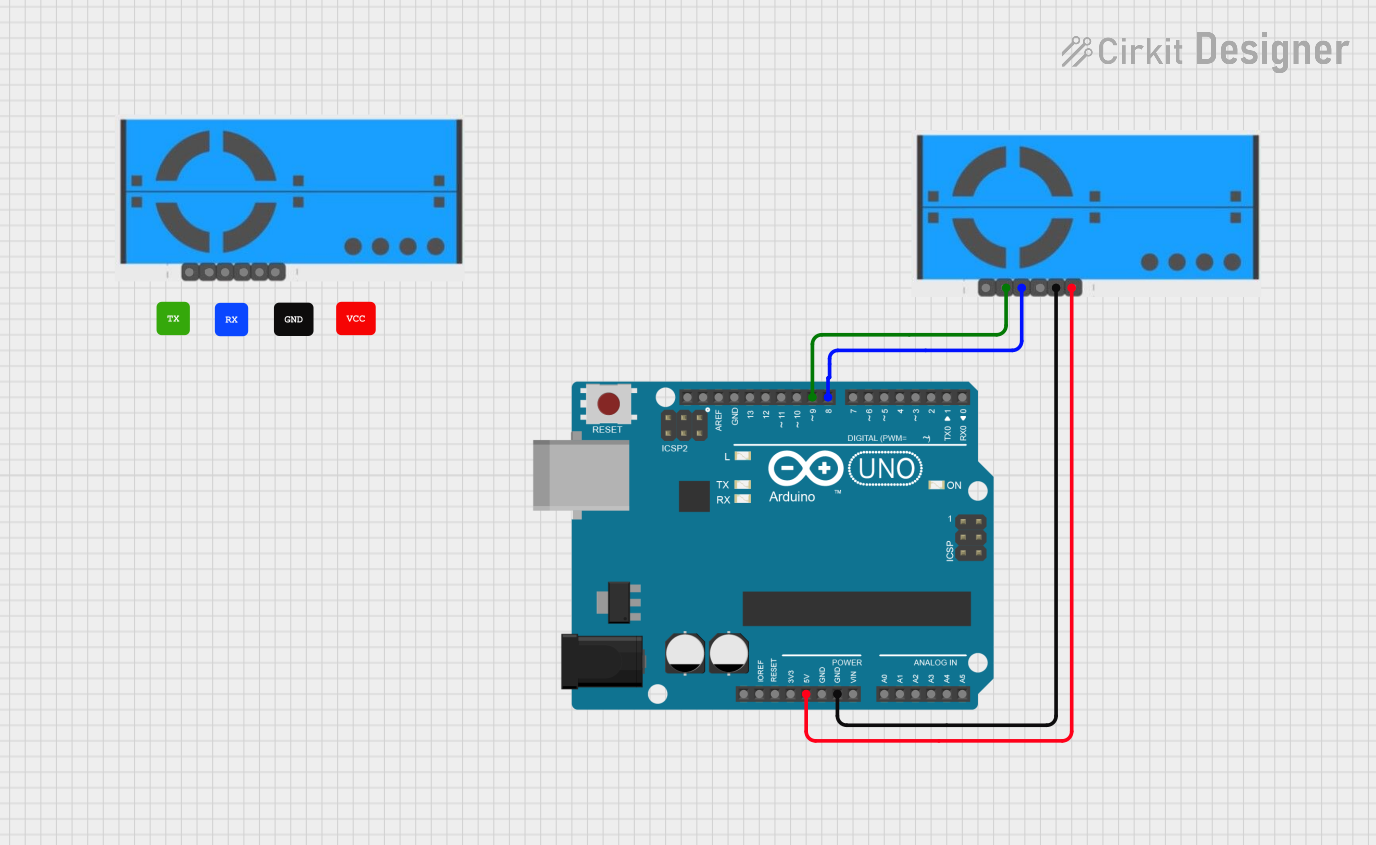
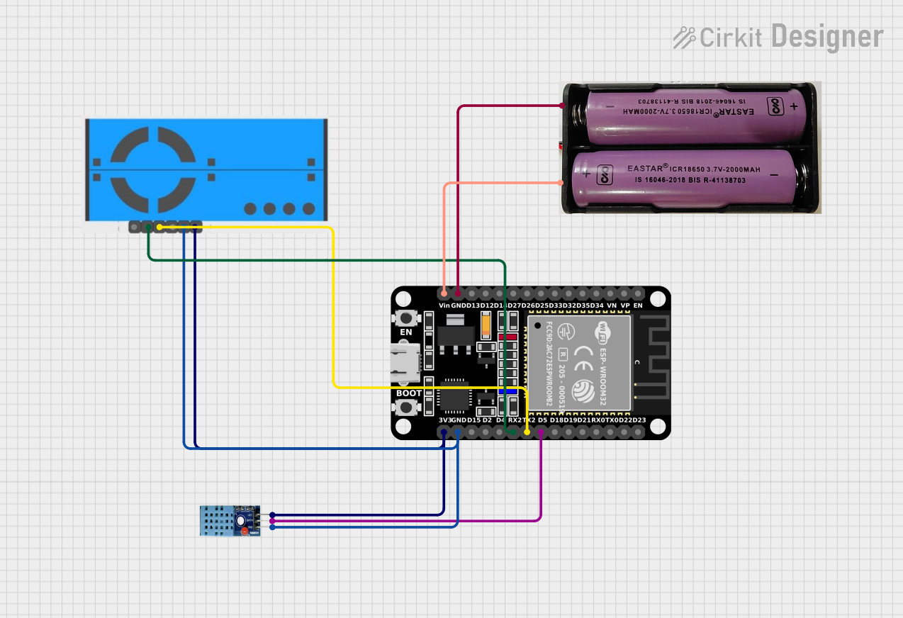
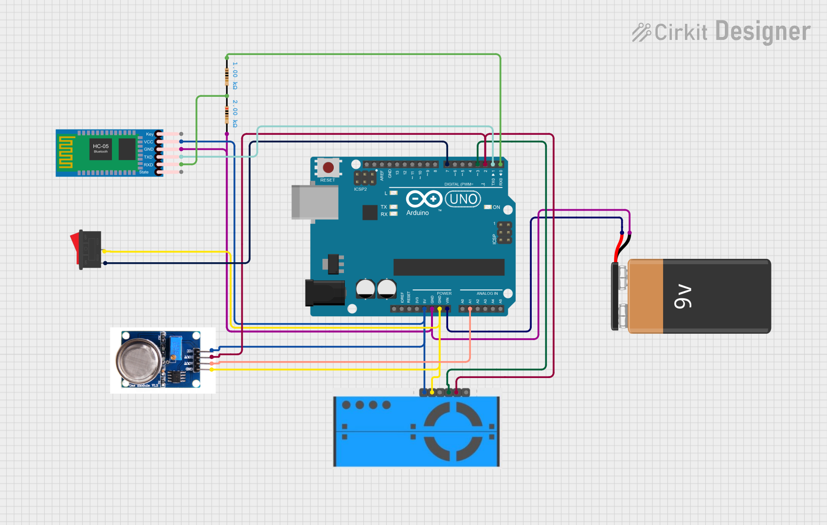
Connecting the PMS5003 to a Circuit
- Power Supply: Connect the
VCCpin to a 5V power source and theGNDpin to ground. - UART Communication: Connect the
TXpin of the PMS5003 to the RX pin of your microcontroller (e.g., Arduino UNO) and theRXpin of the PMS5003 to the TX pin of the microcontroller. - Standby Mode: The
SETpin can be used to put the sensor into standby mode by pulling it low. Leave it unconnected or pull it high for normal operation. - Reset: The
RESETpin can be used to reset the sensor by pulling it low momentarily.
Important Considerations
- Placement: Ensure the sensor is placed in an area with good airflow for accurate readings. Avoid placing it near sources of vibration or strong airflow, as this may affect measurements.
- Warm-Up Time: Allow the sensor to warm up for at least 30 seconds after powering it on to ensure stable readings.
- UART Logic Level: The PMS5003 operates at 3.3V logic levels. If using a 5V microcontroller, use a level shifter to avoid damaging the sensor.
Example Code for Arduino UNO
Below is an example of how to interface the PMS5003 with an Arduino UNO to read PM2.5 data:
#include <SoftwareSerial.h>

// Define the PMS5003 TX and RX pins connected to Arduino
SoftwareSerial pmsSerial(10, 11); // RX, TX

// Buffer to store incoming data from the PMS5003
uint8_t pmsData[32];

void setup() {
  Serial.begin(9600);          // Initialize serial monitor
  pmsSerial.begin(9600);       // Initialize PMS5003 UART communication
  Serial.println("PMS5003 Sensor Initialized");
}

void loop() {
  if (pmsSerial.available() >= 32) { // Check if 32 bytes of data are available
    for (int i = 0; i < 32; i++) {
      pmsData[i] = pmsSerial.read(); // Read data into buffer
    }

    // Verify data header
    if (pmsData[0] == 0x42 && pmsData[1] == 0x4D) {
      // Extract PM2.5 concentration (bytes 12 and 13)
      uint16_t pm25 = (pmsData[12] << 8) | pmsData[13];
      Serial.print("PM2.5 Concentration: ");
      Serial.print(pm25);
      Serial.println(" µg/m³");
    }
  }
}
Notes:
- Connect the PMS5003
TXpin to Arduino pin 10 andRXpin to Arduino pin 11. - Use a level shifter if your Arduino operates at 5V logic levels.
Troubleshooting and FAQs
Common Issues
No Data Output:
- Ensure the sensor is properly powered (check
VCCandGNDconnections). - Verify the UART connections (TX and RX pins) and ensure they are not swapped.
- Check the baud rate (default is 9600 bps).
- Ensure the sensor is properly powered (check
Inaccurate Readings:
- Ensure the sensor is placed in a stable environment with good airflow.
- Avoid exposing the sensor to high humidity or condensation.
Sensor Not Responding:
- Check if the
SETpin is pulled low (standby mode). Pull it high or leave it unconnected for normal operation. - Reset the sensor using the
RESETpin.
- Check if the
FAQs
Q: Can the PMS5003 detect gases like CO2 or VOCs?
A: No, the PMS5003 is designed to measure particulate matter (PM1.0, PM2.5, and PM10) and cannot detect gases.
Q: How often should the sensor be calibrated?
A: The PMS5003 is factory-calibrated and does not require user calibration. However, periodic cleaning of the air inlet and outlet may help maintain accuracy.
Q: Can I use the PMS5003 with a 5V microcontroller?
A: Yes, but you must use a level shifter for the UART communication pins (TX and RX) to avoid damaging the sensor.
Q: What is the lifespan of the PMS5003?
A: The sensor has an estimated lifespan of 3 years under normal operating conditions.