How to Use AS6031_ST: Examples, Pinouts, and Specs
Introduction
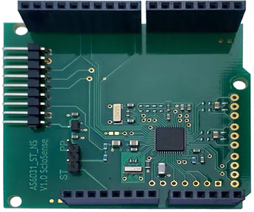
The AS6031_ST is a low-power, high-performance analog sensor interface developed by ScioSense. It is designed to interface with various analog sensors, such as temperature and pressure sensors, and provides integrated signal conditioning for accurate and reliable measurements. The AS6031_ST is particularly well-suited for portable and battery-operated devices due to its low power consumption and compact design.
Explore Projects Built with AS6031_ST


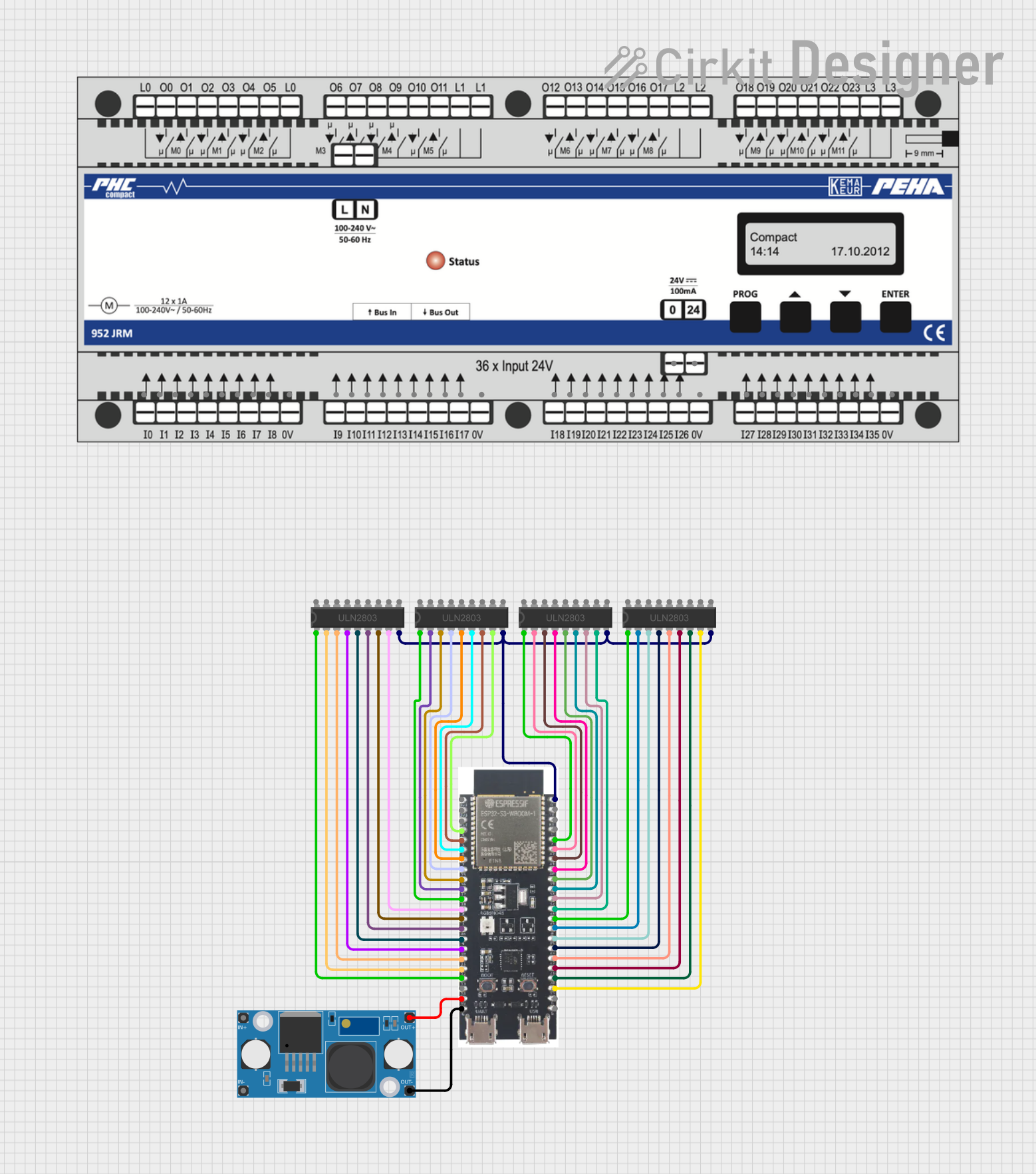
Explore Projects Built with AS6031_ST
Common Applications and Use Cases
- Temperature sensing in industrial and consumer devices
- Pressure sensing in HVAC systems and medical equipment
- Portable and battery-operated devices requiring sensor interfacing
- Environmental monitoring systems
- IoT (Internet of Things) applications
Technical Specifications
The AS6031_ST offers robust performance and flexibility for a wide range of applications. Below are its key technical specifications:
Key Technical Details
| Parameter | Value |
|---|---|
| Supply Voltage (VDD) | 1.8V to 3.6V |
| Operating Current | 100 µA (typical) |
| Standby Current | 1 µA (typical) |
| Input Signal Range | 0V to VDD |
| Output Signal Range | 0V to VDD |
| Operating Temperature | -40°C to +85°C |
| Signal Conditioning | Integrated (amplification, filtering) |
| Sensor Types Supported | Resistive, capacitive, and voltage-output sensors |
| Communication Interface | Analog output |
| Package Type | 16-pin QFN (3mm x 3mm) |
Pin Configuration and Descriptions
The AS6031_ST is housed in a 16-pin QFN package. Below is the pin configuration and description:
| Pin Number | Pin Name | Description |
|---|---|---|
| 1 | VDD | Power supply input (1.8V to 3.6V) |
| 2 | GND | Ground connection |
| 3 | IN+ | Positive input for the sensor signal |
| 4 | IN- | Negative input for the sensor signal |
| 5 | OUT | Analog output signal |
| 6 | NC | No connection (leave unconnected) |
| 7 | NC | No connection (leave unconnected) |
| 8 | NC | No connection (leave unconnected) |
| 9 | NC | No connection (leave unconnected) |
| 10 | NC | No connection (leave unconnected) |
| 11 | NC | No connection (leave unconnected) |
| 12 | NC | No connection (leave unconnected) |
| 13 | NC | No connection (leave unconnected) |
| 14 | NC | No connection (leave unconnected) |
| 15 | NC | No connection (leave unconnected) |
| 16 | NC | No connection (leave unconnected) |
Note: Pins labeled as "NC" should not be connected to any signal or power line.
Usage Instructions
The AS6031_ST is designed to be easy to integrate into a variety of circuits. Below are the steps and considerations for using the component effectively:
How to Use the Component in a Circuit
Power Supply:
- Connect the VDD pin to a stable power supply within the range of 1.8V to 3.6V.
- Connect the GND pin to the ground of the circuit.
Sensor Connection:
- Connect the positive output of the sensor to the IN+ pin.
- Connect the negative output of the sensor to the IN- pin.
Output Signal:
- The processed analog signal will be available at the OUT pin. This can be connected to an ADC (Analog-to-Digital Converter) or other processing circuitry.
Bypass Capacitor:
- Place a 0.1 µF ceramic capacitor close to the VDD pin to ensure stable operation and reduce noise.
Signal Conditioning:
- The AS6031_ST includes integrated signal conditioning, so no external amplification or filtering is required.
Important Considerations and Best Practices
- Ensure that the input signal range does not exceed the specified range of 0V to VDD.
- Avoid connecting any signal or power line to the "NC" pins.
- Use proper grounding techniques to minimize noise and interference.
- If using the AS6031_ST in a battery-operated device, ensure that the power supply is stable and within the specified range to avoid performance issues.
Example: Connecting to an Arduino UNO
The AS6031_ST can be connected to an Arduino UNO for reading and processing the analog output signal. Below is an example of how to interface the AS6031_ST with an Arduino UNO:
Circuit Connections
- VDD: Connect to the 3.3V pin on the Arduino UNO.
- GND: Connect to the GND pin on the Arduino UNO.
- OUT: Connect to an analog input pin (e.g., A0) on the Arduino UNO.
Arduino Code Example
// Define the analog input pin connected to the AS6031_ST OUT pin
const int sensorPin = A0;

void setup() {
  // Initialize serial communication for debugging
  Serial.begin(9600);
}

void loop() {
  // Read the analog value from the AS6031_ST
  int sensorValue = analogRead(sensorPin);

  // Convert the analog value to a voltage (assuming 5V reference)
  float voltage = sensorValue * (5.0 / 1023.0);

  // Print the voltage to the serial monitor
  Serial.print("Sensor Voltage: ");
  Serial.print(voltage);
  Serial.println(" V");

  // Add a small delay for stability
  delay(500);
}
Note: If the Arduino UNO operates at 5V, ensure that the output signal from the AS6031_ST does not exceed 5V. Use a voltage divider if necessary.
Troubleshooting and FAQs
Common Issues and Solutions
No Output Signal:
- Verify that the power supply is within the specified range (1.8V to 3.6V).
- Check the sensor connections to ensure they are properly connected to the IN+ and IN- pins.
Noisy Output Signal:
- Ensure that a bypass capacitor (0.1 µF) is placed close to the VDD pin.
- Check the grounding of the circuit to minimize noise and interference.
Output Signal Out of Range:
- Verify that the input signal from the sensor is within the specified range (0V to VDD).
- Ensure that the sensor is functioning correctly and providing a valid signal.
High Power Consumption:
- Check for any short circuits or incorrect connections.
- Ensure that the AS6031_ST is not operating outside its specified voltage range.
FAQs
Q1: Can the AS6031_ST interface with digital sensors?
A1: No, the AS6031_ST is designed for analog sensors. For digital sensors, a different interface IC would be required.
Q2: What types of sensors are compatible with the AS6031_ST?
A2: The AS6031_ST supports resistive, capacitive, and voltage-output sensors.
Q3: Can the AS6031_ST operate at 5V?
A3: No, the maximum supply voltage for the AS6031_ST is 3.6V. Exceeding this voltage may damage the component.
Q4: Is external signal conditioning required?
A4: No, the AS6031_ST includes integrated signal conditioning, so no external amplification or filtering is needed.
Q5: What is the typical application of the AS6031_ST?
A5: It is commonly used in temperature and pressure sensing applications, especially in portable and battery-operated devices.