How to Use AD7705 Module: Examples, Pinouts, and Specs
AD7705 Module Documentation
1. Introduction
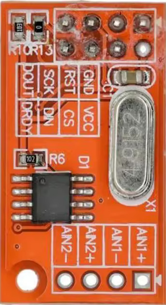
The AD7705 Module is a high-precision, low-power analog-to-digital converter (ADC) designed for applications requiring accurate measurement of analog signals. Manufactured under the part ID AD7705 DO42-2, this module integrates a programmable gain amplifier (PGA) and a serial interface, making it ideal for interfacing with microcontrollers such as the Arduino UNO.
The AD7705 operates with a supply voltage range of 2.7V to 5.25V, making it suitable for battery-powered and low-power applications. Its high resolution and low noise performance make it a popular choice for applications such as:
- Sensor signal conditioning (e.g., temperature, pressure, and strain gauges)
- Data acquisition systems
- Industrial process control
- Portable instrumentation
- Medical devices
2. Technical Specifications
The following table outlines the key technical specifications of the AD7705 module:
| Parameter | Value |
|---|---|
| Supply Voltage (VDD) | 2.7V to 5.25V |
| Power Consumption | 1mW (typical at 3V) |
| Resolution | 16-bit |
| Input Channels | 2 differential or 4 single-ended |
| Input Voltage Range | ±2.5V (with gain = 1) |
| Programmable Gain | 1, 2, 4, 8, 16, 32, 64, 128 |
| Communication Interface | SPI |
| Maximum Clock Frequency | 2.5 MHz |
| Operating Temperature Range | -40°C to +85°C |
Pin Configuration and Descriptions
The AD7705 module typically comes with a 10-pin interface. Below is the pinout and description:
| Pin | Name | Description |
|---|---|---|
| 1 | VDD | Power supply input (2.7V to 5.25V). |
| 2 | GND | Ground connection. |
| 3 | CS | Chip Select (active low). Used to enable communication with the module. |
| 4 | SCLK | Serial Clock. Used to synchronize data transfer with the microcontroller. |
| 5 | DIN | Data Input. Used to send configuration and control data to the AD7705. |
| 6 | DOUT | Data Output. Used to read conversion results from the AD7705. |
| 7 | RESET | Reset pin. Resets the ADC to its default state when pulled low. |
| 8 | AIN1+ | Positive input for Channel 1 (differential mode) or single-ended input. |
| 9 | AIN1- | Negative input for Channel 1 (differential mode) or ground in single-ended. |
| 10 | AIN2+/AIN2- | Positive/Negative input for Channel 2 (differential mode) or single-ended. |
3. Usage Instructions
Connecting the AD7705 to an Arduino UNO
To use the AD7705 module with an Arduino UNO, follow these steps:
Wiring the Module:
- Connect the VDD pin of the AD7705 to the 5V pin of the Arduino.
- Connect the GND pin of the AD7705 to the GND pin of the Arduino.
- Connect the CS pin to any digital pin on the Arduino (e.g., D10).
- Connect the SCLK pin to the Arduino's SPI clock pin (D13).
- Connect the DIN pin to the Arduino's SPI MOSI pin (D11).
- Connect the DOUT pin to the Arduino's SPI MISO pin (D12).
- Optionally, connect the RESET pin to a digital pin on the Arduino for manual reset.
Configuring the AD7705:
- Use the SPI library in Arduino to communicate with the AD7705.
- Configure the ADC's registers to set the desired gain, input channel, and operating mode.
Reading Data:
- Send a command to start a conversion.
- Wait for the conversion to complete (check the status register).
- Read the 16-bit result from the data register.
Example Arduino Code
Below is an example Arduino sketch to interface with the AD7705 module:
#include <SPI.h>

// Pin definitions
const int CS_PIN = 10; // Chip Select pin
const int RESET_PIN = 9; // Reset pin (optional)

// Function to write data to the AD7705
void writeRegister(byte reg, byte value) {
  digitalWrite(CS_PIN, LOW); // Select the AD7705
  SPI.transfer(0x10 | reg);  // Write to the specified register
  SPI.transfer(value);       // Send the value
  digitalWrite(CS_PIN, HIGH); // Deselect the AD7705
}

// Function to read data from the AD7705
unsigned int readData() {
  digitalWrite(CS_PIN, LOW); // Select the AD7705
  SPI.transfer(0x38);        // Command to read data register
  byte highByte = SPI.transfer(0x00); // Read high byte
  byte lowByte = SPI.transfer(0x00);  // Read low byte
  digitalWrite(CS_PIN, HIGH); // Deselect the AD7705
  return (highByte << 8) | lowByte; // Combine high and low bytes
}

void setup() {
  pinMode(CS_PIN, OUTPUT);
  pinMode(RESET_PIN, OUTPUT);
  digitalWrite(CS_PIN, HIGH);
  digitalWrite(RESET_PIN, HIGH);

  SPI.begin(); // Initialize SPI
  SPI.setClockDivider(SPI_CLOCK_DIV16); // Set SPI clock speed
  SPI.setDataMode(SPI_MODE3); // AD7705 uses SPI mode 3

  // Reset the AD7705
  digitalWrite(RESET_PIN, LOW);
  delay(10);
  digitalWrite(RESET_PIN, HIGH);

  // Configure the AD7705
  writeRegister(0x00, 0x40); // Set gain to 1, unipolar mode, and enable channel 1
}

void loop() {
  unsigned int result = readData(); // Read ADC result
  Serial.println(result); // Print the result to the Serial Monitor
  delay(1000); // Wait 1 second before the next reading
}
Important Considerations
- Ensure the input voltage does not exceed the specified range (±2.5V for gain = 1).
- Use proper decoupling capacitors (e.g., 0.1µF) near the power supply pins to reduce noise.
- Avoid long wires for analog inputs to minimize interference and signal degradation.
4. Troubleshooting and FAQs
Common Issues and Solutions
| Issue | Possible Cause | Solution |
|---|---|---|
| No data output from the module | Incorrect wiring or SPI configuration | Verify connections and ensure SPI settings (mode 3, clock speed) are correct. |
| ADC readings are unstable or noisy | Electrical noise or improper grounding | Use shielded cables and ensure proper grounding. |
| Incorrect ADC values | Input voltage exceeds specified range | Ensure input voltage is within the ADC's range (±2.5V for gain = 1). |
| Module not responding | CS pin not properly controlled | Ensure the CS pin is toggled correctly during communication. |
FAQs
Can the AD7705 measure negative voltages?
- Yes, in differential mode, the AD7705 can measure negative voltages within the specified range.
What is the maximum sampling rate of the AD7705?
- The maximum output data rate is approximately 500 Hz.
Can I use the AD7705 with a 3.3V microcontroller?
- Yes, the AD7705 operates with a supply voltage as low as 2.7V, making it compatible with 3.3V systems.
This documentation provides a comprehensive guide to using the AD7705 module. For further assistance, refer to the manufacturer's datasheet or contact technical support.
Explore Projects Built with AD7705 Module


Explore Projects Built with AD7705 Module