How to Use Adafruit PyGamer: Examples, Pinouts, and Specs
Introduction
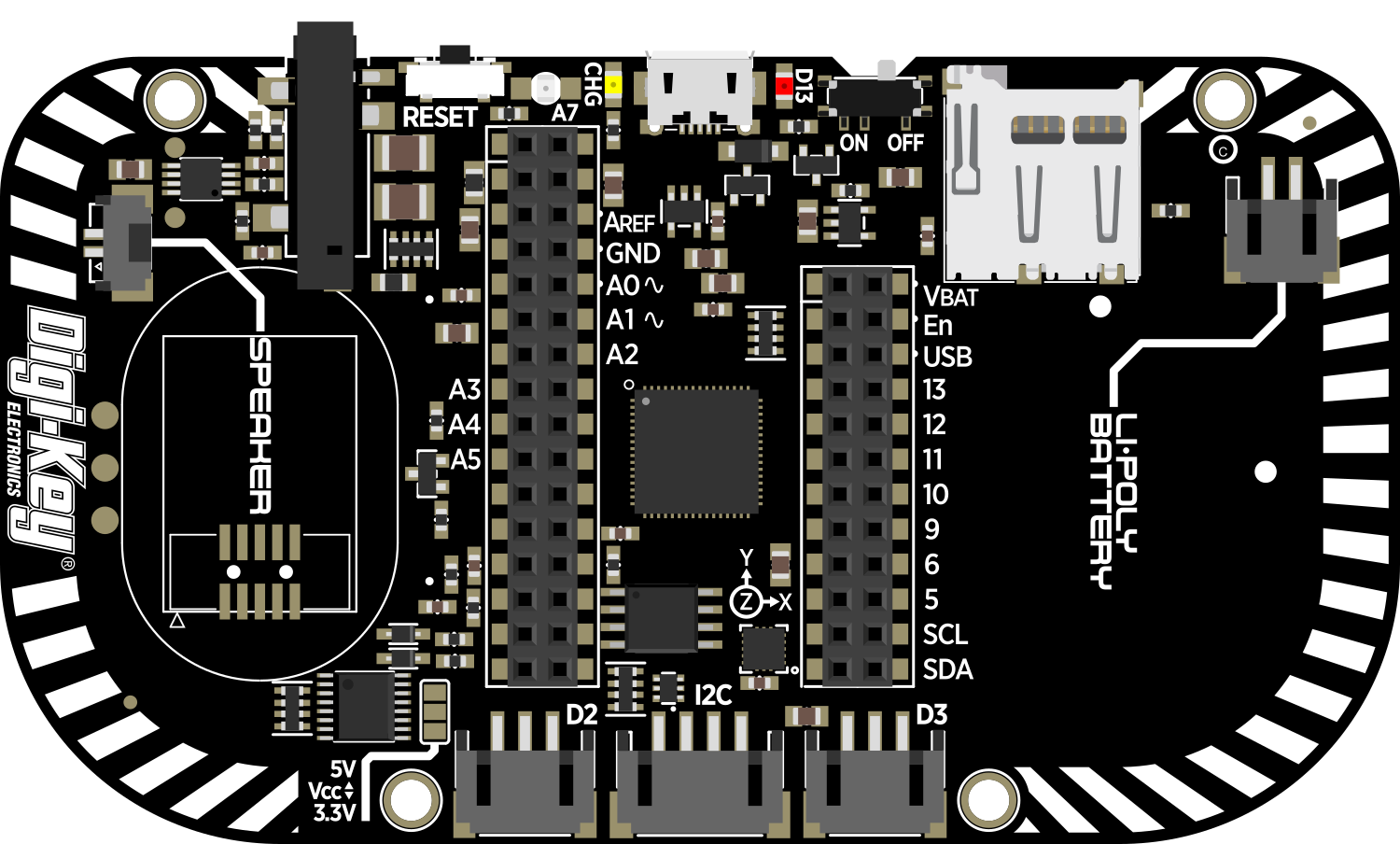
The Adafruit PyGamer is an all-in-one handheld gaming device designed for DIY gaming, electronics projects, and educational purposes. It is powered by the ATSAMD51J19 microcontroller and is capable of running CircuitPython, MakeCode Arcade, or Arduino code. The PyGamer is equipped with a 1.8-inch 160x128 color TFT display, a microSD card slot for expandable storage, a buzzer-speaker for audio output, and a variety of input buttons and a joystick for user interaction. It is an excellent platform for developing retro games, learning programming, and creating interactive projects.
Explore Projects Built with Adafruit PyGamer


Explore Projects Built with Adafruit PyGamer
Common Applications and Use Cases
- DIY handheld gaming
- Educational programming and electronics learning
- Interactive art and music projects
- Prototyping for game design
- Maker fairs and STEM activities
Technical Specifications
Key Technical Details
- Microcontroller: ATSAMD51J19 @ 120 MHz 32-bit ARM Cortex-M4
- Flash Memory: 512 KB
- RAM: 192 KB
- Display: 1.8" 160x128 Color TFT
- Sound: Integrated buzzer-speaker
- Input: D-pad, A/B buttons, Home, Start, Select, and analog joystick
- Storage: microSD card slot
- Connectivity: JST connectors for I2C and UART, 4-pin STEMMA connector
- Power: 3.7V LiPo battery connector, USB or 5V DC jack
Pin Configuration and Descriptions
| Pin Number | Function | Description |
|---|---|---|
| 1 | A Button | Gamepad A button input |
| 2 | B Button | Gamepad B button input |
| 3 | Joystick X | Analog joystick X-axis |
| 4 | Joystick Y | Analog joystick Y-axis |
| 5 | Start Button | Gamepad Start button input |
| 6 | Select Button | Gamepad Select button input |
| 7 | D-Pad Up | Gamepad D-pad up input |
| 8 | D-Pad Down | Gamepad D-pad down input |
| 9 | D-Pad Left | Gamepad D-pad left input |
| 10 | D-Pad Right | Gamepad D-pad right input |
| 11 | Light Sensor | Ambient light sensor |
| 12 | NeoPixel | Addressable RGB LED (NeoPixel) |
| 13 | Speaker | Buzzer-speaker output |
| 14 | SD Card Detect | MicroSD card insertion detection |
| 15 | Battery | Battery voltage monitoring |
| 16 | 3.3V | 3.3V power output |
| 17 | GND | Ground |
Usage Instructions
How to Use the Component in a Circuit
Powering the Device: The PyGamer can be powered via the USB connection, a 3.7V LiPo battery, or a 5V DC jack. Ensure that the power source is connected properly before use.
Programming the Device: Connect the PyGamer to your computer using a USB cable. The device should be recognized as a removable disk. You can drag and drop your CircuitPython or Arduino code onto the device.
Using the Display: The TFT display can be accessed using the Adafruit libraries for CircuitPython or Arduino. Initialize the display in your code to start drawing graphics or text.
Reading Inputs: The buttons and joystick can be read using digital and analog input pins, respectively. Use the appropriate libraries and functions to detect button presses and joystick movements.
Audio Output: To play sounds, use the buzzer-speaker with the audio libraries available for CircuitPython or Arduino.
Expandable Storage: To use the microSD card slot, insert a formatted microSD card and use the SD card libraries to read and write files.
Important Considerations and Best Practices
- Always disconnect the power source before making any changes to the hardware.
- When handling the device, be mindful of electrostatic discharge (ESD) and take appropriate precautions.
- Ensure that the battery is charged and in good condition if using a LiPo battery.
- Keep the device firmware and libraries up to date for the best performance and compatibility.
Troubleshooting and FAQs
Common Issues
- Device Not Recognized: Ensure the USB cable is properly connected and the computer's USB port is functioning. Try a different USB port or cable if necessary.
- Display Issues: Check that the display initialization code is correct and that the libraries are properly installed.
- Button/Input Not Responding: Verify the button connections and ensure that the code is correctly reading the input pins.
- Sound Not Working: Confirm that the speaker is enabled in the code and that the volume is set appropriately.
Solutions and Tips for Troubleshooting
- Restart the device by disconnecting and reconnecting the power source.
- Check for loose connections or damaged components.
- Review the code for errors or incorrect pin assignments.
- Consult the Adafruit forums or online communities for help with specific issues.
FAQs
Q: Can I use the PyGamer with languages other than CircuitPython or Arduino?
A: The PyGamer is primarily designed for use with CircuitPython and Arduino. Other programming environments may be supported, but functionality could be limited.
Q: How do I update the firmware on the PyGamer?
A: Firmware updates can be done by downloading the latest UF2 file from Adafruit and dragging it onto the PYGAMERBOOT drive that appears when the device is in bootloader mode.
Q: What is the maximum size of the microSD card that the PyGamer can support?
A: The PyGamer typically supports microSD cards up to 32GB, but larger cards formatted as FAT32 may also work.
Q: Can I connect additional sensors or components to the PyGamer?
A: Yes, the PyGamer has JST connectors for I2C and UART, as well as a 4-pin STEMMA connector for easy expansion.
For more detailed information and resources, visit the Adafruit Learning System or the PyGamer product page.