How to Use L293D: Examples, Pinouts, and Specs
Introduction
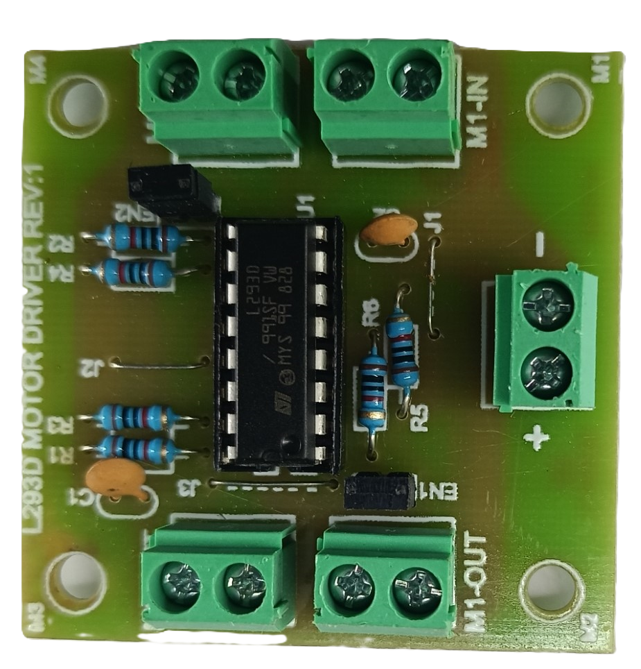
The L293D is a quadruple high-current half-H driver designed to provide bidirectional drive currents of up to 600 mA at voltages from 4.5 V to 36 V. It is equipped with diodes for back EMF protection, making it ideal for driving inductive loads such as DC and stepping motors, relays, and solenoids. The L293D is widely used in robotics, automation projects, and other applications requiring motor control.
Explore Projects Built with L293D
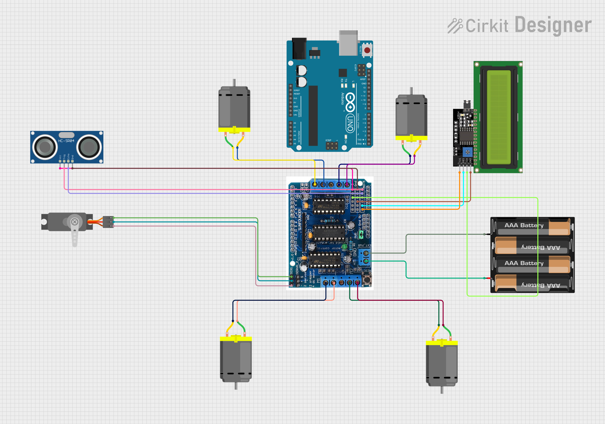

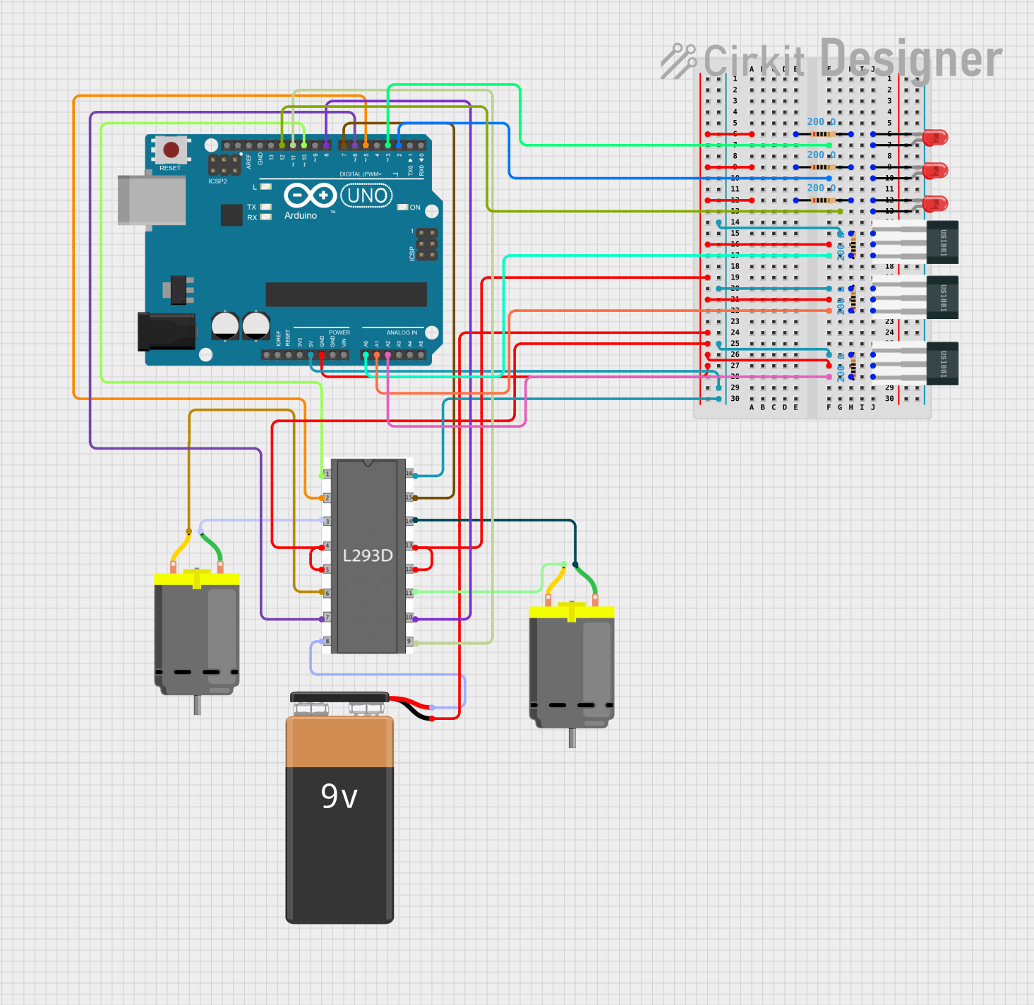
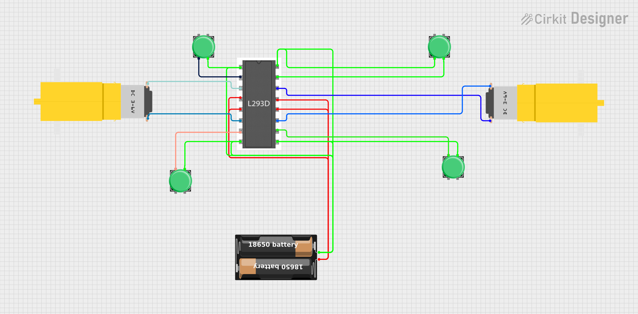
Explore Projects Built with L293D
Technical Specifications
Key Technical Details
- Supply Voltage (Vcc1): 4.5 V to 36 V
- Logic Supply Voltage (Vcc2): 4.5 V to 7 V
- Output Current (each channel): Up to 600 mA
- Peak Output Current (each channel): 1.2 A (non-repetitive)
- Output Clamp Diodes: For inductive transient suppression
- Operating Temperature: -40°C to +150°C
Pin Configuration and Descriptions
| Pin Number | Name | Description |
|---|---|---|
| 1 | 1,2EN | Enable pin for motor 1,2; active high |
| 2 | 1A | Input 1 for motor 1 |
| 3 | 1Y | Output 1 for motor 1 |
| 4 | GND | Ground |
| 5 | GND | Ground |
| 6 | 2Y | Output 2 for motor 1 |
| 7 | 2A | Input 2 for motor 1 |
| 8 | Vcc2 | Logic supply voltage |
| 9 | 3,4EN | Enable pin for motor 2,3; active high |
| 10 | 3A | Input 1 for motor 2 |
| 11 | 3Y | Output 1 for motor 2 |
| 12 | GND | Ground |
| 13 | GND | Ground |
| 14 | 4Y | Output 2 for motor 2 |
| 15 | 4A | Input 2 for motor 2 |
| 16 | Vcc1 | Motor supply voltage |
Usage Instructions
How to Use the L293D in a Circuit
- Connect the motor supply voltage (up to 36V) to pin 16 (Vcc1).
- Connect the logic supply voltage (4.5V to 7V) to pin 8 (Vcc2).
- Connect the ground pins (4, 5, 12, 13) to the system ground.
- Apply the input signals to the input pins (1A, 2A for motor 1 and 3A, 4A for motor 2).
- Enable the motors by setting the enable pins (1,2EN for motor 1 and 3,4EN for motor 2) to high.
- The output pins (1Y, 2Y for motor 1 and 3Y, 4Y for motor 2) will provide the drive to the motors.
Important Considerations and Best Practices
- Use a separate power supply for Vcc1 to handle motor currents and avoid noise in the logic circuits.
- Always use flyback diodes when driving inductive loads to prevent damage from back EMF.
- Ensure that the current through the outputs does not exceed the maximum rating of 600 mA per channel.
- Provide adequate heat sinking if the IC is expected to handle high currents for extended periods.
Example Code for Arduino UNO
// Define the L293D connections to the Arduino
const int motorPin1 = 3; // Input 1 for motor 1
const int motorPin2 = 4; // Input 2 for motor 1
const int enablePin = 9; // Enable pin for motor 1

void setup() {
  // Set motor pins as outputs
  pinMode(motorPin1, OUTPUT);
  pinMode(motorPin2, OUTPUT);
  pinMode(enablePin, OUTPUT);

  // Enable the motor
  digitalWrite(enablePin, HIGH);
}

void loop() {
  // Spin the motor in one direction
  digitalWrite(motorPin1, HIGH);
  digitalWrite(motorPin2, LOW);
  delay(2000);

  // Spin the motor in the opposite direction
  digitalWrite(motorPin1, LOW);
  digitalWrite(motorPin2, HIGH);
  delay(2000);

  // Stop the motor
  digitalWrite(motorPin1, LOW);
  digitalWrite(motorPin2, LOW);
  delay(2000);
}
Troubleshooting and FAQs
Common Issues
- Motor not spinning: Check if the enable pin is set high and the input pins are receiving the correct logic signals.
- Overheating: Ensure the current through the motor and IC does not exceed the maximum ratings. Consider adding a heat sink.
- Inconsistent motor operation: Verify that the power supply can handle the motor's current draw without significant voltage drops.
Solutions and Tips
- Double-check wiring and connections for any loose contacts or shorts.
- Use a multimeter to verify the voltage levels at the input and enable pins.
- Ensure that the logic supply voltage (Vcc2) is within the specified range for proper operation.
FAQs
Q: Can the L293D drive two motors simultaneously? A: Yes, the L293D can drive two motors at the same time, with one motor connected to outputs 1Y and 2Y and the other to 3Y and 4Y.
Q: What is the purpose of the diodes in the L293D? A: The diodes provide protection against inductive voltage spikes (back EMF) when driving inductive loads like motors.
Q: Can I use the L293D to drive a stepper motor? A: Yes, the L293D can be used to drive a bipolar stepper motor by controlling the current in each coil in the correct sequence.
This documentation provides a comprehensive guide to using the L293D motor driver IC in various applications. For further information, consult the manufacturer's datasheet and application notes.