How to Use esp32 c3 super mini: Examples, Pinouts, and Specs
Introduction
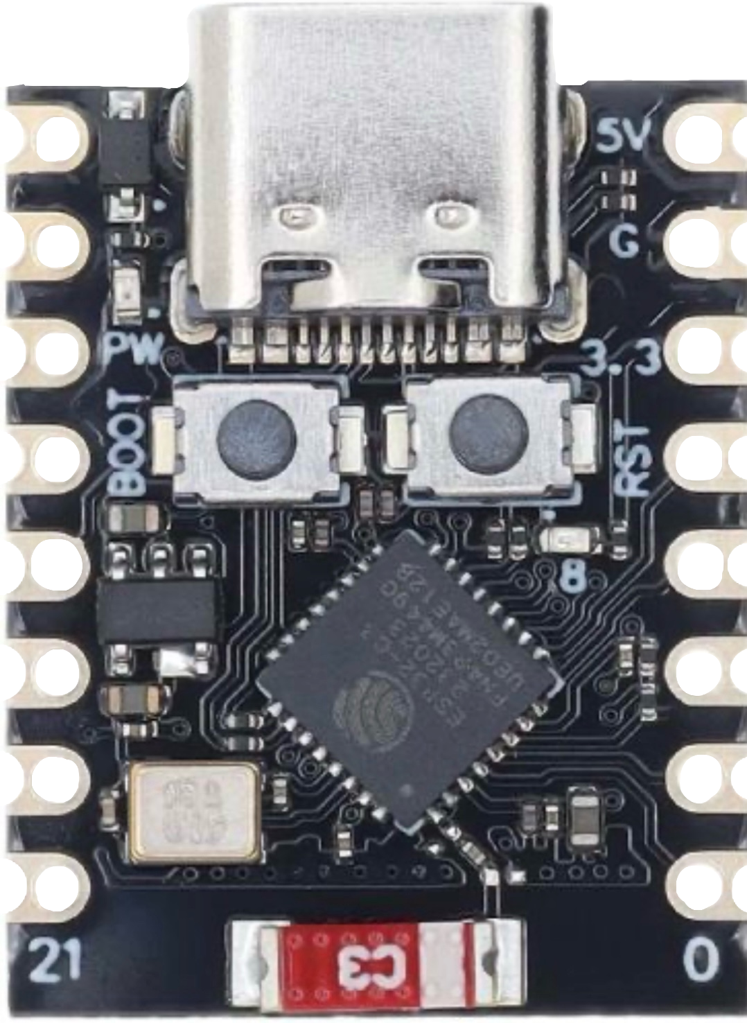
The ESP32-C3 Super Mini, manufactured by Espressif, is a compact and powerful microcontroller designed for IoT applications and embedded systems. It features integrated Wi-Fi and Bluetooth Low Energy (BLE) capabilities, making it an excellent choice for wireless communication projects. Its small form factor and low power consumption make it ideal for portable and space-constrained designs.
Explore Projects Built with esp32 c3 super mini


Explore Projects Built with esp32 c3 super mini
Common Applications and Use Cases
- Smart home devices (e.g., smart plugs, light controllers)
- Wearable technology
- Industrial IoT sensors and controllers
- Wireless data logging and monitoring
- Prototyping for Wi-Fi and BLE-enabled projects
Technical Specifications
The ESP32-C3 Super Mini is based on the ESP32-C3 SoC, which is a RISC-V-based microcontroller. Below are its key technical details:
Key Technical Details
- Processor: 32-bit RISC-V single-core processor, up to 160 MHz
- Flash Memory: 4 MB (onboard)
- RAM: 400 KB SRAM
- Wireless Connectivity:
- Wi-Fi: 802.11 b/g/n (2.4 GHz)
- Bluetooth: BLE 5.0
- Operating Voltage: 3.3V
- GPIO Pins: 15 (multipurpose, including ADC, PWM, I2C, SPI, UART)
- Power Consumption: Ultra-low power in deep sleep mode (~5 µA)
- Dimensions: 18 mm x 18 mm (approx.)
Pin Configuration and Descriptions
The ESP32-C3 Super Mini has a compact pinout. Below is the pin configuration:
| Pin Name | Function | Description |
|---|---|---|
| 3V3 | Power Input | 3.3V power supply input. |
| GND | Ground | Ground connection. |
| GPIO0 | General Purpose I/O | Can be used for input/output, ADC, or other functions. |
| GPIO1 | General Purpose I/O | Multipurpose pin, supports UART TX. |
| GPIO2 | General Purpose I/O | Multipurpose pin, supports UART RX. |
| GPIO3 | General Purpose I/O | Multipurpose pin, supports I2C SDA. |
| GPIO4 | General Purpose I/O | Multipurpose pin, supports I2C SCL. |
| GPIO5 | General Purpose I/O | Multipurpose pin, supports SPI MOSI. |
| GPIO6 | General Purpose I/O | Multipurpose pin, supports SPI MISO. |
| GPIO7 | General Purpose I/O | Multipurpose pin, supports SPI CLK. |
| EN | Enable | Active-high enable pin. Pull low to reset the module. |
| RST | Reset | Active-low reset pin. |
| TXD | UART Transmit | UART transmit pin for serial communication. |
| RXD | UART Receive | UART receive pin for serial communication. |
| ADC | Analog Input | 12-bit ADC input for analog signal reading. |
Usage Instructions
The ESP32-C3 Super Mini is versatile and easy to use in a variety of projects. Below are the steps and best practices for using it effectively.
How to Use the Component in a Circuit
Powering the Module:
- Provide a stable 3.3V power supply to the
3V3pin. - Connect the
GNDpin to the ground of your circuit.
- Provide a stable 3.3V power supply to the
Programming the Module:
- Use a USB-to-UART adapter to connect the
TXDandRXDpins to your computer. - Install the ESP32 board package in the Arduino IDE or use Espressif's ESP-IDF for advanced development.
- Select "ESP32-C3 Dev Module" as the board in the Arduino IDE.
- Use a USB-to-UART adapter to connect the
Connecting Peripherals:
- Use the GPIO pins for digital input/output, PWM, or communication protocols like I2C, SPI, and UART.
- For analog input, connect your sensor to the
ADCpin.
Uploading Code:
- Press and hold the
ENbutton while uploading code to put the module in bootloader mode. - Release the
ENbutton once the upload starts.
- Press and hold the
Important Considerations and Best Practices
- Voltage Levels: Ensure all connected peripherals operate at 3.3V logic levels to avoid damaging the module.
- Antenna Placement: Avoid placing metal objects near the onboard antenna to maintain optimal Wi-Fi and BLE performance.
- Power Supply: Use a low-noise, stable power supply to prevent unexpected resets or performance issues.
- Deep Sleep Mode: Use deep sleep mode to conserve power in battery-operated projects.
Example Code for Arduino UNO
Below is an example of how to use the ESP32-C3 Super Mini to blink an LED connected to GPIO2:
// Example: Blink an LED using ESP32-C3 Super Mini
// Connect an LED to GPIO2 with a current-limiting resistor.

#define LED_PIN 2  // GPIO2 is connected to the LED

void setup() {
  pinMode(LED_PIN, OUTPUT);  // Set GPIO2 as an output pin
}

void loop() {
  digitalWrite(LED_PIN, HIGH);  // Turn the LED on
  delay(1000);                 // Wait for 1 second
  digitalWrite(LED_PIN, LOW);   // Turn the LED off
  delay(1000);                 // Wait for 1 second
}
Troubleshooting and FAQs
Common Issues and Solutions
Module Not Detected by Computer:
- Ensure the USB-to-UART adapter is properly connected to the
TXDandRXDpins. - Check that the correct drivers for the USB-to-UART adapter are installed.
- Ensure the USB-to-UART adapter is properly connected to the
Code Upload Fails:
- Verify that the correct board and port are selected in the Arduino IDE.
- Hold the
ENbutton during the upload process to enter bootloader mode.
Wi-Fi Connection Issues:
- Ensure the Wi-Fi credentials in your code are correct.
- Check for interference or weak signal strength near the module.
Module Overheating:
- Verify that the input voltage does not exceed 3.3V.
- Ensure proper ventilation around the module.
FAQs
Q: Can the ESP32-C3 Super Mini operate on 5V?
A: No, the module operates at 3.3V. Connecting 5V directly to the 3V3 pin may damage the module.
Q: How many devices can connect to the ESP32-C3 via BLE?
A: The ESP32-C3 supports up to 50 BLE connections, depending on the application and memory usage.
Q: Can I use the ESP32-C3 Super Mini with MicroPython?
A: Yes, the ESP32-C3 is compatible with MicroPython. You can flash the MicroPython firmware to the module and use it for development.
Q: Does the module support OTA updates?
A: Yes, the ESP32-C3 supports Over-The-Air (OTA) updates, allowing you to update firmware wirelessly.
By following this documentation, you can effectively integrate the ESP32-C3 Super Mini into your projects and troubleshoot common issues.