How to Use IR GAS SENSOR: Examples, Pinouts, and Specs
Introduction
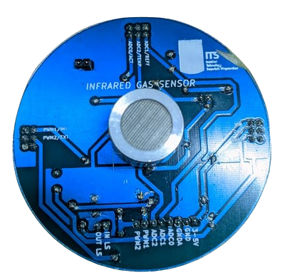
An IR gas sensor detects the presence of specific gases in the environment by measuring the absorption of infrared light. This non-contact method of gas detection is highly reliable and widely used in various industries. The sensor operates based on the principle that gases absorb infrared light at specific wavelengths, allowing for accurate identification and concentration measurement of the target gas.
Explore Projects Built with IR GAS SENSOR
Explore Projects Built with IR GAS SENSOR
Common Applications and Use Cases
- Industrial safety systems for detecting hazardous gases
- Environmental monitoring for air quality analysis
- Gas leak detection in residential and commercial settings
- Automotive applications for exhaust gas analysis
- Medical devices for respiratory gas monitoring
Technical Specifications
Below are the key technical details of a typical IR gas sensor:
| Parameter | Value |
|---|---|
| Operating Voltage | 3.3V to 5V |
| Operating Current | 30mA to 50mA |
| Detection Range | 0 to 100% volume (varies by gas) |
| Response Time | < 30 seconds |
| Operating Temperature | -20°C to 50°C |
| Humidity Range | 0% to 95% RH (non-condensing) |
| Output Signal | Analog voltage or digital signal |
| Wavelength Sensitivity | 2.5µm to 14µm (infrared spectrum) |
Pin Configuration and Descriptions
The pinout of an IR gas sensor may vary depending on the model. Below is a general pin configuration:
| Pin | Name | Description |
|---|---|---|
| 1 | VCC | Power supply input (3.3V to 5V) |
| 2 | GND | Ground connection |
| 3 | OUT | Analog or digital output signal |
| 4 | EN (optional) | Enable pin to activate or deactivate the sensor |
Usage Instructions
How to Use the Component in a Circuit
- Power the Sensor: Connect the VCC pin to a 3.3V or 5V power source and the GND pin to the ground.
- Read the Output:
- For analog sensors, connect the OUT pin to an analog input pin of a microcontroller (e.g., Arduino).
- For digital sensors, connect the OUT pin to a digital input pin.
- Enable the Sensor: If the sensor has an enable (EN) pin, connect it to a HIGH signal to activate the sensor.
- Calibrate the Sensor: Allow the sensor to warm up for a few minutes to stabilize its readings.
Important Considerations and Best Practices
- Avoid Condensation: Ensure the sensor is used in a non-condensing environment to prevent damage.
- Proper Ventilation: Place the sensor in an area with adequate airflow for accurate gas detection.
- Calibration: Periodically calibrate the sensor to maintain accuracy, especially in critical applications.
- Power Supply: Use a stable power source to avoid fluctuations in sensor readings.
Example: Connecting to an Arduino UNO
Below is an example of how to interface an IR gas sensor with an Arduino UNO:
Circuit Connections
- Connect the sensor's VCC pin to the Arduino's 5V pin.
- Connect the sensor's GND pin to the Arduino's GND pin.
- Connect the sensor's OUT pin to the Arduino's A0 pin (analog input).
Arduino Code
// IR Gas Sensor Example Code
// This code reads the analog output of the IR gas sensor and displays the
// gas concentration on the serial monitor.

const int sensorPin = A0; // Analog pin connected to the sensor's OUT pin

void setup() {
  Serial.begin(9600); // Initialize serial communication at 9600 baud
  pinMode(sensorPin, INPUT); // Set the sensor pin as input
}

void loop() {
  int sensorValue = analogRead(sensorPin); // Read the analog value from the sensor
  float voltage = sensorValue * (5.0 / 1023.0); // Convert the value to voltage
  Serial.print("Sensor Voltage: ");
  Serial.print(voltage);
  Serial.println(" V");

  // Add your gas concentration calculation here if applicable
  delay(1000); // Wait for 1 second before the next reading
}
Troubleshooting and FAQs
Common Issues and Solutions
No Output Signal
- Cause: Incorrect wiring or insufficient power supply.
- Solution: Double-check the connections and ensure the power supply meets the sensor's requirements.
Inaccurate Readings
- Cause: Sensor not calibrated or exposed to extreme environmental conditions.
- Solution: Calibrate the sensor and ensure it operates within the specified temperature and humidity range.
Slow Response Time
- Cause: Poor ventilation or gas diffusion.
- Solution: Place the sensor in an area with better airflow.
Sensor Not Detected by Microcontroller
- Cause: Faulty sensor or incorrect pin configuration.
- Solution: Test the sensor with a multimeter and verify the pin connections.
FAQs
Q1: Can the IR gas sensor detect multiple gases simultaneously?
A1: Most IR gas sensors are designed to detect a specific gas. For multiple gases, you may need a multi-gas sensor or multiple sensors.
Q2: How often should the sensor be calibrated?
A2: Calibration frequency depends on the application. For critical applications, calibrate monthly or as recommended by the manufacturer.
Q3: Can the sensor be used outdoors?
A3: Yes, but ensure it is protected from direct sunlight, rain, and extreme environmental conditions.
Q4: What gases can an IR gas sensor detect?
A4: Common gases include CO2, CH4 (methane), and hydrocarbons. Check the sensor's datasheet for specific gas compatibility.