Cirkit Designer Logo
Cirkit Designer
Your all-in-one circuit design IDE
Home / 
Component Documentation

How to Use SSR-40A: Examples, Pinouts, and Specs

Image of SSR-40A
Cirkit Designer LogoDesign with SSR-40A in Cirkit Designer

Introduction

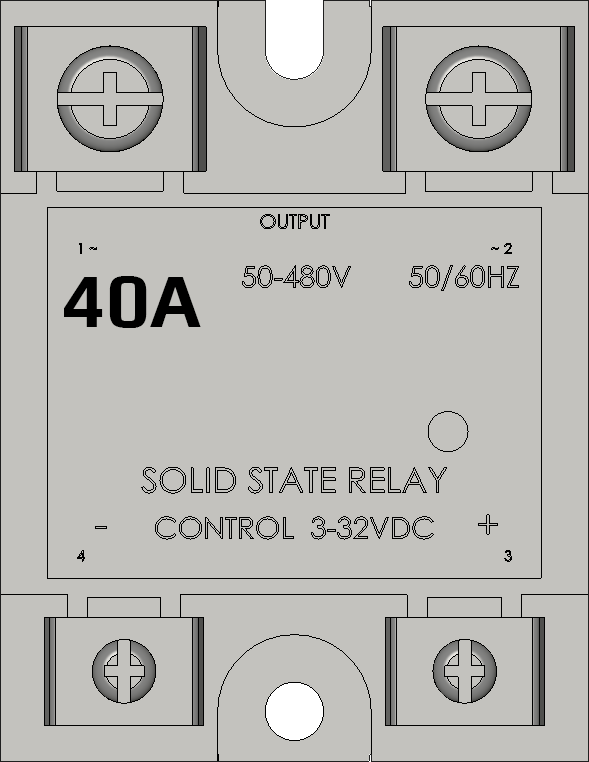
The SSR-40A is a Solid State Relay (SSR) designed to switch high currents using semiconductor devices. Unlike electromechanical relays, SSRs provide faster switching times, longer life spans, and silent operation. The '40A' denotes its maximum current handling capability of 40 Amperes, making it suitable for a variety of high-power applications such as industrial automation, motor control, and temperature control systems.

Explore Projects Built with SSR-40A

Use Cirkit Designer to design, explore, and prototype these projects online. Some projects support real-time simulation. Click "Open Project" to start designing instantly!
Temperature-Controlled Heating System with SSR and Titanium Resistor
Image of Wire Cut Four Slider 33-2 & 33-3 (Old): A project utilizing SSR-40A in a practical application
This circuit is a temperature control system that uses a temperature controller to regulate a heating titanium resistor via a solid-state relay (SSR). The power transformer supplies the necessary voltage to the temperature controller, which in turn controls the SSR to manage the heating element.
Cirkit Designer LogoOpen Project in Cirkit Designer
Satellite-Based Timing and Navigation System with SDR and Atomic Clock Synchronization
Image of GPS 시스템 측정 구성도_Confirm: A project utilizing SSR-40A in a practical application
This circuit appears to be a complex system involving power supply management, GPS and timing synchronization, and data communication. It includes a SI-TEX G1 Satellite Compass for GPS data, an XHTF1021 Atomic Rubidium Clock for precise timing, and Ettus USRP B200 units for software-defined radio communication. Power is supplied through various SMPS units and distributed via terminal blocks and DC jacks. Data communication is facilitated by Beelink MINI S12 N95 computers, RS232 splitters, and a 1000BASE-T Media Converter for network connectivity. RF Directional Couplers are used to interface antennas with the USRP units, and the entire system is likely contained within cases for protection and organization.
Cirkit Designer LogoOpen Project in Cirkit Designer
PID Temperature Control System with Thermocouple and SSR
Image of IR: A project utilizing SSR-40A in a practical application
This circuit is a temperature control system that uses a thermocouple to measure temperature and a PID controller to regulate it. The PID controller drives a solid-state relay (SSR) to control an external load, with power supplied through an AC inlet socket.
Cirkit Designer LogoOpen Project in Cirkit Designer
Satellite Compass and Network-Integrated GPS Data Processing System
Image of GPS 시스템 측정 구성도_241016: A project utilizing SSR-40A in a practical application
This circuit comprises a satellite compass, a mini PC, two GPS antennas, power supplies, a network switch, media converters, and an atomic rubidium clock. The satellite compass is powered by a triple output DC power supply and interfaces with an RS232 splitter for 1PPS signals. The mini PCs are connected to the USRP B200 devices via USB for data and power, and to media converters via Ethernet, which in turn connect to a network switch using fiber optic links. The antennas are connected to the USRP B200s through RF directional couplers, and the atomic clock provides a 1PPS input to the RS232 splitter.
Cirkit Designer LogoOpen Project in Cirkit Designer

Explore Projects Built with SSR-40A

Use Cirkit Designer to design, explore, and prototype these projects online. Some projects support real-time simulation. Click "Open Project" to start designing instantly!
Image of Wire Cut Four Slider 33-2 & 33-3 (Old): A project utilizing SSR-40A in a practical application
Temperature-Controlled Heating System with SSR and Titanium Resistor
This circuit is a temperature control system that uses a temperature controller to regulate a heating titanium resistor via a solid-state relay (SSR). The power transformer supplies the necessary voltage to the temperature controller, which in turn controls the SSR to manage the heating element.
Cirkit Designer LogoOpen Project in Cirkit Designer
Image of GPS 시스템 측정 구성도_Confirm: A project utilizing SSR-40A in a practical application
Satellite-Based Timing and Navigation System with SDR and Atomic Clock Synchronization
This circuit appears to be a complex system involving power supply management, GPS and timing synchronization, and data communication. It includes a SI-TEX G1 Satellite Compass for GPS data, an XHTF1021 Atomic Rubidium Clock for precise timing, and Ettus USRP B200 units for software-defined radio communication. Power is supplied through various SMPS units and distributed via terminal blocks and DC jacks. Data communication is facilitated by Beelink MINI S12 N95 computers, RS232 splitters, and a 1000BASE-T Media Converter for network connectivity. RF Directional Couplers are used to interface antennas with the USRP units, and the entire system is likely contained within cases for protection and organization.
Cirkit Designer LogoOpen Project in Cirkit Designer
Image of IR: A project utilizing SSR-40A in a practical application
PID Temperature Control System with Thermocouple and SSR
This circuit is a temperature control system that uses a thermocouple to measure temperature and a PID controller to regulate it. The PID controller drives a solid-state relay (SSR) to control an external load, with power supplied through an AC inlet socket.
Cirkit Designer LogoOpen Project in Cirkit Designer
Image of GPS 시스템 측정 구성도_241016: A project utilizing SSR-40A in a practical application
Satellite Compass and Network-Integrated GPS Data Processing System
This circuit comprises a satellite compass, a mini PC, two GPS antennas, power supplies, a network switch, media converters, and an atomic rubidium clock. The satellite compass is powered by a triple output DC power supply and interfaces with an RS232 splitter for 1PPS signals. The mini PCs are connected to the USRP B200 devices via USB for data and power, and to media converters via Ethernet, which in turn connect to a network switch using fiber optic links. The antennas are connected to the USRP B200s through RF directional couplers, and the atomic clock provides a 1PPS input to the RS232 splitter.
Cirkit Designer LogoOpen Project in Cirkit Designer

Technical Specifications

Key Technical Details

  • Load Voltage Range: Typically 24-380V AC
  • Control Voltage Range: 3-32V DC
  • Maximum Load Current: 40A
  • Isolation Voltage: >2500V AC
  • Switching Speed: Typically <10ms
  • Operating Temperature: -30°C to +75°C

Pin Configuration and Descriptions

Pin Number Description Notes
1 Control Voltage (+) Connect to DC+ (3-32V)
2 Control Voltage (-) Connect to DC-
3 Load Voltage (AC) Connect to AC load
4 Load Voltage (AC) Connect to AC line

Usage Instructions

How to Use the SSR-40A in a Circuit

  1. Connect the Control Voltage:

    • Connect the positive control voltage (3-32V DC) to Pin 1.
    • Connect the negative control voltage to Pin 2.
  2. Connect the Load:

    • Connect one side of the AC load to Pin 3.
    • Connect the other side of the AC load to the AC line (neutral or phase as required by your application).
  3. Testing:

    • Apply the control voltage to the SSR and verify that the load operates as expected.

Important Considerations and Best Practices

  • Heat Dissipation: Ensure proper heat sinking for the SSR, as high currents can generate significant heat.
  • Protective Measures: Use a fuse or circuit breaker rated for the load to protect against overcurrent conditions.
  • Inductive Loads: For inductive loads (like motors), consider using a snubber circuit to protect the SSR from voltage spikes.
  • Isolation: Maintain proper isolation between the low-voltage control side and the high-voltage load side.

Troubleshooting and FAQs

Common Issues

  • SSR Not Switching: Verify control voltage is within specified range and connections are secure.
  • Overheating: Ensure adequate heat sinking and airflow around the SSR.

Solutions and Tips

  • No Load Response: Check if the input signal is present and within the specified range.
  • Excessive Heat: Review the current rating of the load to ensure it does not exceed 40A. Improve heat dissipation if necessary.

FAQs

Q: Can the SSR-40A be used with DC loads? A: No, this SSR is designed for AC loads. Using it with DC loads can damage the SSR.

Q: Is it necessary to use a heat sink? A: Yes, for loads approaching the 40A limit, a heat sink is crucial to prevent overheating.

Q: How do I know if the SSR is functioning properly? A: When control voltage is applied, the load should activate. If not, check the control signal and load connections.

Example Arduino Code

// Define the SSR control pin
const int ssrPin = 7;

void setup() {
  // Set the SSR pin as an output
  pinMode(ssrPin, OUTPUT);
}

void loop() {
  // Turn on the SSR (activate the connected AC load)
  digitalWrite(ssrPin, HIGH);
  delay(5000); // Keep the load on for 5 seconds

  // Turn off the SSR (deactivate the connected AC load)
  digitalWrite(ssrPin, LOW);
  delay(5000); // Keep the load off for 5 seconds
}

Note: The above code assumes the SSR control voltage is compatible with the Arduino output voltage and that the SSR is connected to pin 7. Always ensure the control voltage matches the SSR's requirements.