Cirkit Designer Logo
Cirkit Designer
Your all-in-one circuit design IDE
Home / 
Component Documentation

How to Use SGP41 Breakout: Examples, Pinouts, and Specs

Image of SGP41 Breakout
Cirkit Designer LogoDesign with SGP41 Breakout in Cirkit Designer

Introduction

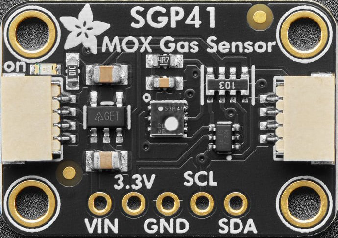
The SGP41 Breakout (Manufacturer Part ID: 6455) by Adafruit is a compact and user-friendly circuit board designed to interface with the SGP41 gas sensor. This sensor specializes in detecting air quality parameters, including Total Volatile Organic Compounds (TVOCs) and equivalent CO2 (eCO2) levels. The breakout board simplifies integration by including essential components for power regulation and signal conditioning, making it ideal for both hobbyists and professionals.

Explore Projects Built with SGP41 Breakout

Use Cirkit Designer to design, explore, and prototype these projects online. Some projects support real-time simulation. Click "Open Project" to start designing instantly!
ESP32-Powered NTP Clock with Multiple GC9A01 Displays
Image of InfoOrbsFork: A project utilizing SGP41 Breakout in a practical application
This circuit features an ESP32 microcontroller connected to multiple GC9A01 displays and a USB Type C breakout for power. The ESP32 runs a sketch to retrieve the current time from an NTP server over WiFi and displays the hours and minutes across the GC9A01 displays, with each display showing a single digit or colon separator. Pushbuttons are connected to GPIOs on the ESP32, potentially for user input to control display functions or settings.
Cirkit Designer LogoOpen Project in Cirkit Designer
Arduino UNO Controlled Servo Motors with Button Interface
Image of BRAS ROBOT: A project utilizing SGP41 Breakout in a practical application
This circuit features an Arduino UNO microcontroller interfaced with an Adafruit PCA9685 PWM Servo Breakout board to control multiple SG90 servo motors. The servos are actuated using a set of push buttons connected to the Arduino, with each pair of buttons increasing or decreasing the angle of a corresponding servo. The system is powered by a 5V battery connected to the PWM breakout board, which in turn powers the servos and the Arduino.
Cirkit Designer LogoOpen Project in Cirkit Designer
ESP32-Controlled Multi-Axis Actuator System with Orientation Sensing and Light Detection
Image of Auto_Level_Table: A project utilizing SGP41 Breakout in a practical application
This circuit features an ESP32 S3 N32R8V microcontroller interfaced with multiple IBT-2 H-Bridge Motor Drivers to control several Linear Actuators, and it receives input from KY-018 LDR Photo Resistors and Pushbuttons. The ESP32 is powered by a 5V supply from an Adafruit MPM3610 5V Buck Converter, while the Linear Actuators and Motor Drivers are powered by a 12V 7Ah battery. Additionally, the ESP32 communicates with an Adafruit BNO085 9-DOF Orientation IMU Fusion Breakout for orientation sensing.
Cirkit Designer LogoOpen Project in Cirkit Designer
ESP32-Based Audio Player with GPS and SD Card Storage
Image of Kidventure: A project utilizing SGP41 Breakout in a practical application
This circuit features an ESP32 microcontroller connected to a GPS NEO 6M module, an INMP441 microphone, a Max98357 audio amplifier, a MicroSD card breakout board, and a loudspeaker. The ESP32 is configured to communicate with the GPS module via serial connection, record audio through the microphone using I2S, play audio via the amplifier, and read/write data to the MicroSD card. The embedded code on the ESP32 is set up to use Google TTS (Text-To-Speech) to generate speech that is output through the loudspeaker.
Cirkit Designer LogoOpen Project in Cirkit Designer

Explore Projects Built with SGP41 Breakout

Use Cirkit Designer to design, explore, and prototype these projects online. Some projects support real-time simulation. Click "Open Project" to start designing instantly!
Image of InfoOrbsFork: A project utilizing SGP41 Breakout in a practical application
ESP32-Powered NTP Clock with Multiple GC9A01 Displays
This circuit features an ESP32 microcontroller connected to multiple GC9A01 displays and a USB Type C breakout for power. The ESP32 runs a sketch to retrieve the current time from an NTP server over WiFi and displays the hours and minutes across the GC9A01 displays, with each display showing a single digit or colon separator. Pushbuttons are connected to GPIOs on the ESP32, potentially for user input to control display functions or settings.
Cirkit Designer LogoOpen Project in Cirkit Designer
Image of BRAS ROBOT: A project utilizing SGP41 Breakout in a practical application
Arduino UNO Controlled Servo Motors with Button Interface
This circuit features an Arduino UNO microcontroller interfaced with an Adafruit PCA9685 PWM Servo Breakout board to control multiple SG90 servo motors. The servos are actuated using a set of push buttons connected to the Arduino, with each pair of buttons increasing or decreasing the angle of a corresponding servo. The system is powered by a 5V battery connected to the PWM breakout board, which in turn powers the servos and the Arduino.
Cirkit Designer LogoOpen Project in Cirkit Designer
Image of Auto_Level_Table: A project utilizing SGP41 Breakout in a practical application
ESP32-Controlled Multi-Axis Actuator System with Orientation Sensing and Light Detection
This circuit features an ESP32 S3 N32R8V microcontroller interfaced with multiple IBT-2 H-Bridge Motor Drivers to control several Linear Actuators, and it receives input from KY-018 LDR Photo Resistors and Pushbuttons. The ESP32 is powered by a 5V supply from an Adafruit MPM3610 5V Buck Converter, while the Linear Actuators and Motor Drivers are powered by a 12V 7Ah battery. Additionally, the ESP32 communicates with an Adafruit BNO085 9-DOF Orientation IMU Fusion Breakout for orientation sensing.
Cirkit Designer LogoOpen Project in Cirkit Designer
Image of Kidventure: A project utilizing SGP41 Breakout in a practical application
ESP32-Based Audio Player with GPS and SD Card Storage
This circuit features an ESP32 microcontroller connected to a GPS NEO 6M module, an INMP441 microphone, a Max98357 audio amplifier, a MicroSD card breakout board, and a loudspeaker. The ESP32 is configured to communicate with the GPS module via serial connection, record audio through the microphone using I2S, play audio via the amplifier, and read/write data to the MicroSD card. The embedded code on the ESP32 is set up to use Google TTS (Text-To-Speech) to generate speech that is output through the loudspeaker.
Cirkit Designer LogoOpen Project in Cirkit Designer

Common Applications

  • Indoor air quality monitoring
  • Smart home automation systems
  • HVAC (Heating, Ventilation, and Air Conditioning) systems
  • IoT (Internet of Things) environmental sensing
  • Industrial air quality control

Technical Specifications

Key Technical Details

Parameter Value
Sensor Type Gas sensor for TVOC and eCO2
Operating Voltage 3.3V to 5V
Communication Interface I2C
I2C Address 0x59 (default)
Operating Temperature Range -10°C to +50°C
Power Consumption ~2.6 mA (typical)
Dimensions 25.4mm x 17.8mm x 4.6mm

Pin Configuration and Descriptions

Pin Name Description
VIN Power input (3.3V to 5V). Connect to the power supply of your microcontroller.
GND Ground. Connect to the ground of your circuit.
SCL I2C clock line. Connect to the SCL pin of your microcontroller.
SDA I2C data line. Connect to the SDA pin of your microcontroller.
INT Interrupt pin (optional). Can be used for advanced configurations.

Usage Instructions

How to Use the SGP41 Breakout in a Circuit

  1. Power the Breakout Board: Connect the VIN pin to a 3.3V or 5V power source and the GND pin to ground.
  2. Connect I2C Lines: Use the SCL and SDA pins to connect the breakout board to the I2C bus of your microcontroller.
  3. Install Required Libraries: If using an Arduino, install the Adafruit SGP41 Library via the Arduino Library Manager.
  4. Write or Upload Code: Use the provided example code or write your own to read TVOC and eCO2 data from the sensor.

Important Considerations and Best Practices

  • I2C Pull-Up Resistors: Ensure your I2C bus has appropriate pull-up resistors (typically 4.7kΩ). Many microcontroller boards include these by default.
  • Avoid Contaminants: Keep the sensor away from liquids, dust, and other contaminants that could affect its accuracy.
  • Warm-Up Time: Allow the sensor to warm up for a few seconds after powering it on for accurate readings.
  • Ventilation: Ensure proper airflow around the sensor for reliable air quality measurements.

Example Code for Arduino UNO

#include <Wire.h>
#include "Adafruit_SGP41.h"

// Create an SGP41 object
Adafruit_SGP41 sgp41;

void setup() {
  Serial.begin(115200);
  while (!Serial) delay(10); // Wait for Serial Monitor to open

  Serial.println("SGP41 Breakout Example");

  // Initialize the sensor
  if (!sgp41.begin()) {
    Serial.println("Failed to find SGP41 sensor! Check wiring.");
    while (1) delay(10);
  }
  Serial.println("SGP41 sensor initialized.");
}

void loop() {
  uint16_t tvoc, eco2;

  // Perform a measurement
  if (!sgp41.measureRawSignals(tvoc, eco2)) {
    Serial.println("Failed to read from SGP41 sensor!");
    return;
  }

  // Print the results
  Serial.print("TVOC: ");
  Serial.print(tvoc);
  Serial.print(" ppb, eCO2: ");
  Serial.print(eco2);
  Serial.println(" ppm");

  delay(1000); // Wait 1 second before the next reading
}

Troubleshooting and FAQs

Common Issues

  1. Sensor Not Detected

    • Cause: Incorrect wiring or I2C address mismatch.
    • Solution: Double-check the connections and ensure the I2C address is set to 0x59.
  2. Inaccurate Readings

    • Cause: Insufficient warm-up time or poor ventilation.
    • Solution: Allow the sensor to warm up for a few seconds and ensure proper airflow.
  3. I2C Communication Errors

    • Cause: Missing pull-up resistors or incorrect I2C connections.
    • Solution: Verify that pull-up resistors are present and that the SCL and SDA lines are correctly connected.

FAQs

Q: Can the SGP41 Breakout be powered with 5V?
A: Yes, the breakout board includes a voltage regulator, allowing it to be powered with 3.3V or 5V.

Q: What is the default I2C address of the SGP41?
A: The default I2C address is 0x59.

Q: How often should I take measurements?
A: For most applications, taking measurements every 1-2 seconds is sufficient.

Q: Can I use the SGP41 Breakout with a Raspberry Pi?
A: Yes, the SGP41 Breakout is compatible with Raspberry Pi. Use the I2C pins and an appropriate library, such as Adafruit's Python library for the SGP41.

Q: Does the sensor require calibration?
A: The SGP41 is factory-calibrated and does not require additional calibration for typical use cases.