How to Use Photon2: Examples, Pinouts, and Specs
Introduction
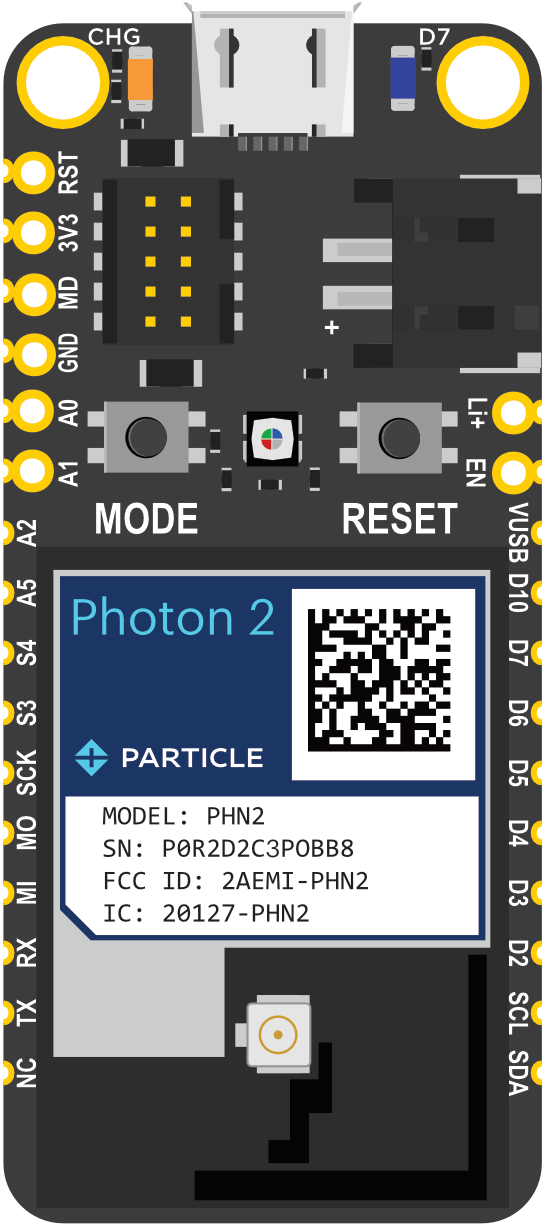
The Photon2 is a versatile microcontroller development board equipped with Wi-Fi and Bluetooth capabilities, making it an ideal choice for Internet of Things (IoT) applications. This powerful board is designed to facilitate rapid prototyping and development of connected devices, offering a robust platform for both beginners and experienced developers.
Explore Projects Built with Photon2
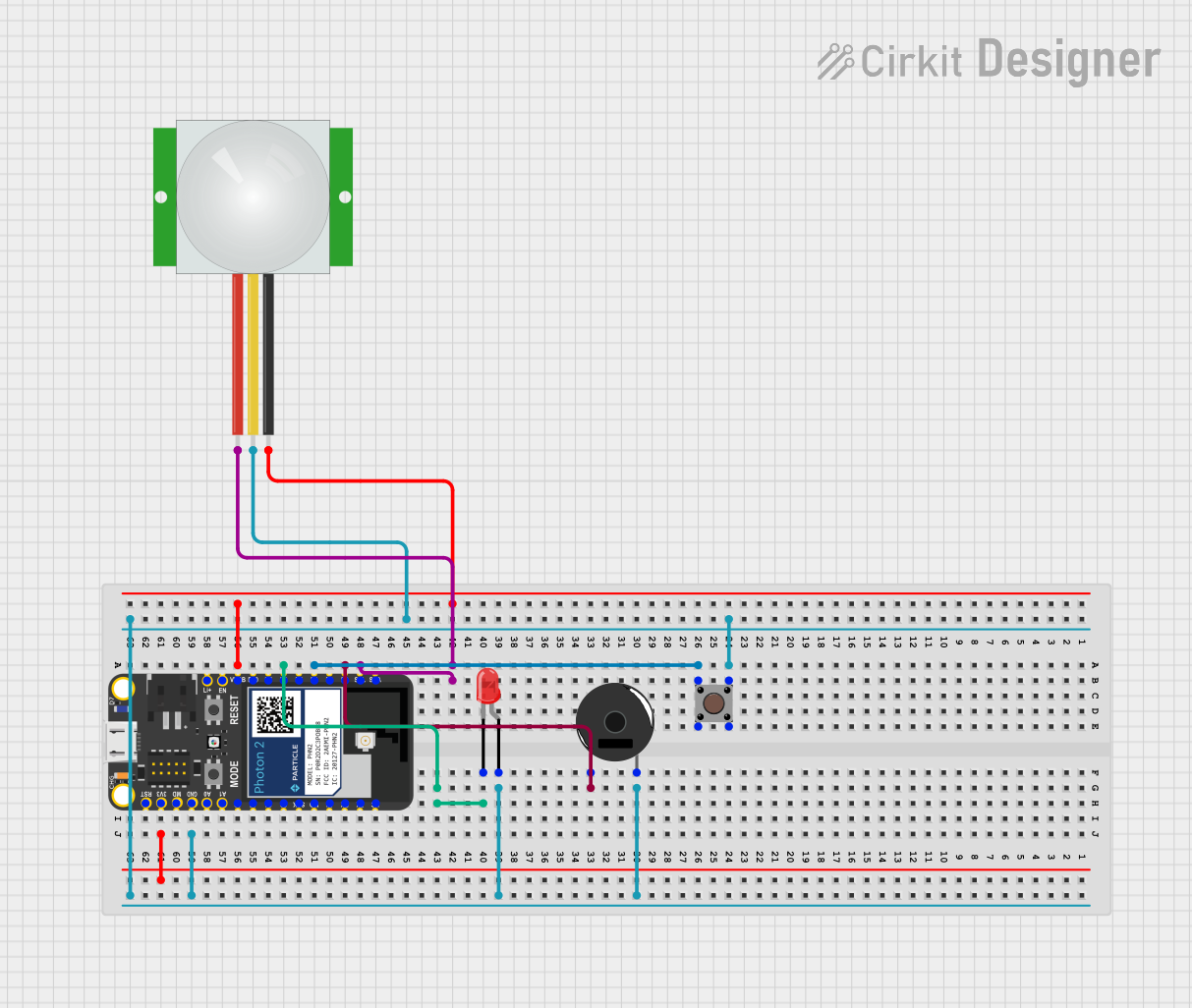
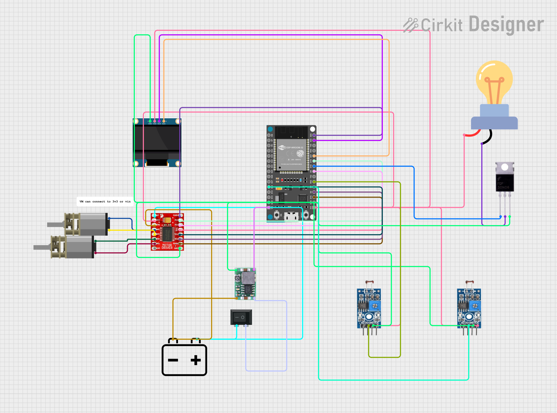
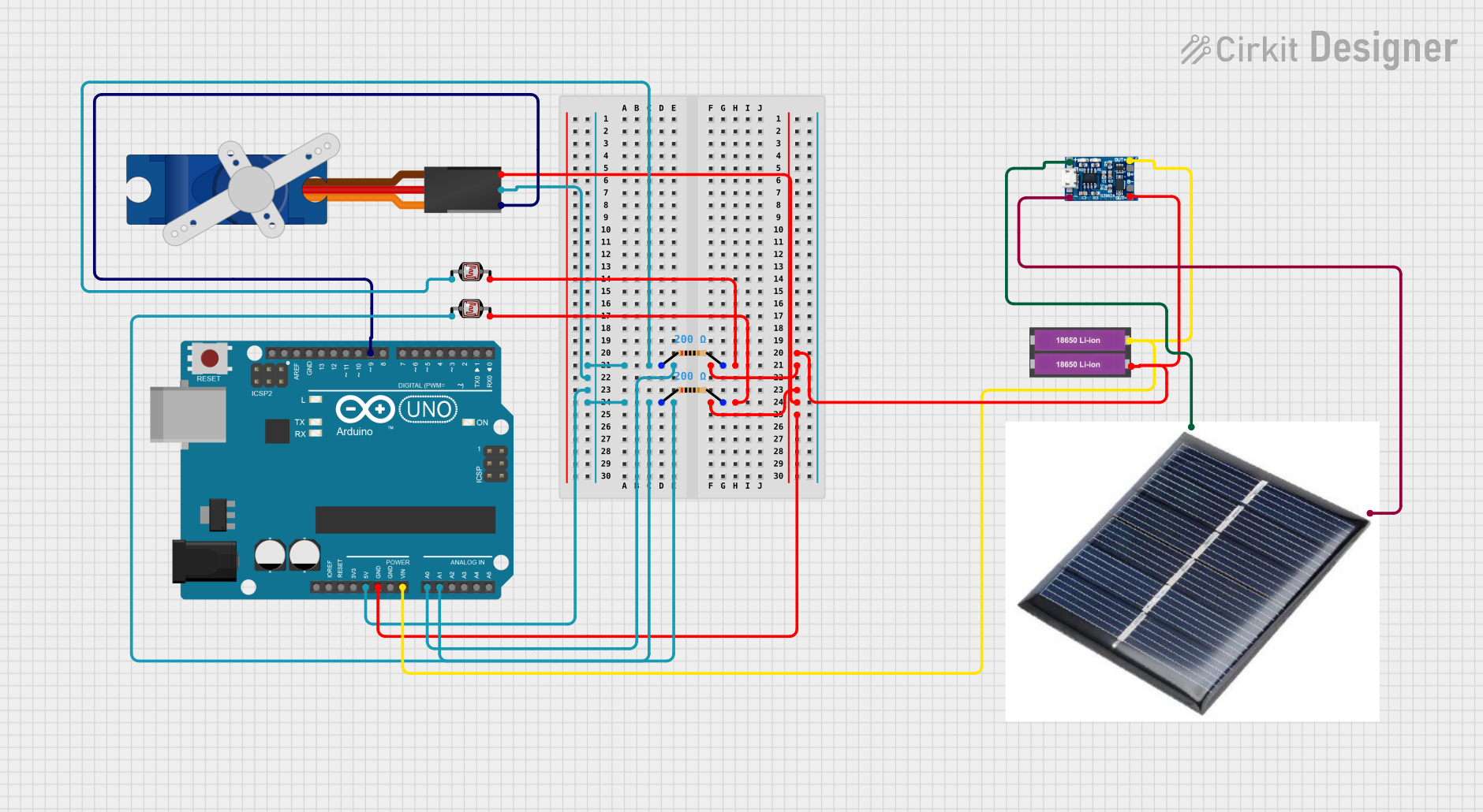
Explore Projects Built with Photon2
Common Applications and Use Cases
- Home Automation: Control and monitor home appliances remotely.
- Wearable Devices: Develop smart wearable gadgets with connectivity features.
- Industrial Automation: Implement IoT solutions for industrial monitoring and control.
- Environmental Monitoring: Collect and transmit environmental data such as temperature, humidity, and air quality.
- Smart Agriculture: Monitor and manage agricultural conditions and equipment.
Technical Specifications
Key Technical Details
| Specification | Value |
|---|---|
| Microcontroller | ARM Cortex-M4 |
| Operating Voltage | 3.3V |
| Input Voltage | 5V (via USB) |
| Digital I/O Pins | 18 |
| Analog Input Pins | 8 |
| Flash Memory | 1MB |
| SRAM | 256KB |
| Clock Speed | 120 MHz |
| Wi-Fi | 802.11 b/g/n |
| Bluetooth | 4.2 (BLE) |
| Dimensions | 36mm x 24mm |
Pin Configuration and Descriptions
| Pin Number | Pin Name | Description |
|---|---|---|
| 1 | VIN | Input voltage (5V) |
| 2 | GND | Ground |
| 3 | 3V3 | 3.3V output |
| 4 | A0 | Analog input 0 |
| 5 | A1 | Analog input 1 |
| 6 | A2 | Analog input 2 |
| 7 | A3 | Analog input 3 |
| 8 | A4 | Analog input 4 |
| 9 | A5 | Analog input 5 |
| 10 | D0 | Digital I/O 0 |
| 11 | D1 | Digital I/O 1 |
| 12 | D2 | Digital I/O 2 |
| 13 | D3 | Digital I/O 3 |
| 14 | D4 | Digital I/O 4 |
| 15 | D5 | Digital I/O 5 |
| 16 | D6 | Digital I/O 6 |
| 17 | D7 | Digital I/O 7 |
| 18 | RX | UART Receive |
| 19 | TX | UART Transmit |
| 20 | RST | Reset |
Usage Instructions
How to Use the Photon2 in a Circuit
Powering the Board:
- Connect the VIN pin to a 5V power source or use the USB port for power.
- Ensure the GND pin is connected to the ground of your power source.
Connecting Sensors and Actuators:
- Use the digital I/O pins (D0-D7) for connecting digital sensors and actuators.
- Use the analog input pins (A0-A5) for connecting analog sensors.
Programming the Board:
- Connect the Photon2 to your computer via USB.
- Use the Arduino IDE or other compatible development environments to write and upload code.
Important Considerations and Best Practices
- Voltage Levels: Ensure that all connected components operate at 3.3V logic levels to avoid damaging the board.
- Pin Usage: Avoid using the same pin for multiple functions simultaneously.
- Wi-Fi and Bluetooth: Be mindful of the power consumption when using Wi-Fi and Bluetooth features.
Example Code
Here is an example code to read an analog sensor value and send it over Wi-Fi to a server:
#include <WiFi.h>

// Replace with your network credentials
const char* ssid = "your_SSID";
const char* password = "your_PASSWORD";

// Server details
const char* server = "your_server_address";
const int port = 80;

void setup() {
  Serial.begin(115200);
  pinMode(A0, INPUT);

  // Connect to Wi-Fi
  WiFi.begin(ssid, password);
  while (WiFi.status() != WL_CONNECTED) {
    delay(1000);
    Serial.println("Connecting to WiFi...");
  }
  Serial.println("Connected to WiFi");
}

void loop() {
  int sensorValue = analogRead(A0);
  Serial.print("Sensor Value: ");
  Serial.println(sensorValue);

  // Connect to server
  WiFiClient client;
  if (client.connect(server, port)) {
    client.print("GET /update?value=");
    client.print(sensorValue);
    client.println(" HTTP/1.1");
    client.println("Host: your_server_address");
    client.println("Connection: close");
    client.println();
  }
  client.stop();

  delay(10000); // Send data every 10 seconds
}
Troubleshooting and FAQs
Common Issues Users Might Face
Wi-Fi Connection Problems:
- Ensure the SSID and password are correct.
- Check if the Wi-Fi network is operational.
Analog Readings Are Inaccurate:
- Verify the sensor connections.
- Ensure the sensor operates within the 3.3V range.
Board Not Recognized by Computer:
- Check the USB cable and port.
- Install the necessary drivers for the Photon2.
Solutions and Tips for Troubleshooting
- Reset the Board: Press the RST button to reset the board if it becomes unresponsive.
- Check Power Supply: Ensure the board is receiving adequate power.
- Update Firmware: Keep the board's firmware updated to the latest version for optimal performance.
By following this documentation, you should be able to effectively utilize the Photon2 microcontroller development board in your IoT projects. Happy prototyping!