How to Use Arduino 101: Examples, Pinouts, and Specs
Introduction
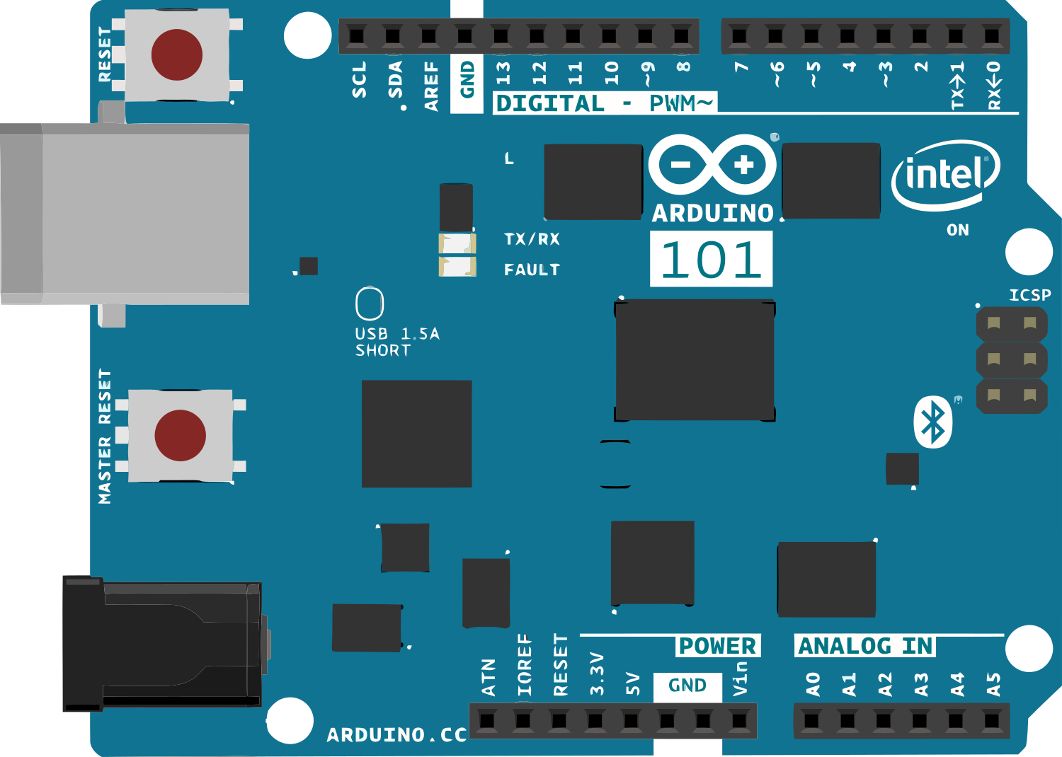
The Arduino 101 is a microcontroller board based on the Intel Curie module. It combines the simplicity of Arduino with advanced features such as built-in Bluetooth Low Energy (BLE) capabilities and a 6-axis accelerometer/gyroscope. This board is ideal for projects requiring wireless communication, motion sensing, and real-time control. Its versatility makes it suitable for applications in IoT, robotics, wearable devices, and educational projects.
Common applications include:
- Wireless sensor networks
- Motion tracking and gesture recognition
- IoT devices with BLE connectivity
- Robotics and automation systems
- Educational tools for learning embedded systems
Explore Projects Built with Arduino 101

Explore Projects Built with Arduino 101
Technical Specifications
The Arduino 101 offers a range of features and capabilities that make it a powerful tool for developers and hobbyists alike.
Key Technical Details
| Specification | Value |
|---|---|
| Microcontroller | Intel Curie module |
| Operating Voltage | 3.3V |
| Input Voltage (recommended) | 7-12V |
| Input Voltage (limit) | 7-20V |
| Digital I/O Pins | 14 (4 PWM outputs) |
| Analog Input Pins | 6 |
| DC Current per I/O Pin | 20 mA |
| Flash Memory | 196 KB (96 KB for user applications) |
| SRAM | 24 KB |
| Clock Speed | 32 MHz |
| Bluetooth | Bluetooth Low Energy (BLE) |
| Sensors | 6-axis accelerometer/gyroscope |
| USB Connector | Micro USB |
Pin Configuration and Descriptions
| Pin Number | Pin Name | Description |
|---|---|---|
| 0-13 | Digital I/O | General-purpose digital input/output pins |
| 3, 5, 6, 9 | PWM | Pulse Width Modulation capable pins |
| A0-A5 | Analog Input | Analog input pins (10-bit resolution) |
| VIN | VIN | Input voltage to the board (7-12V) |
| 3.3V | 3.3V Output | Regulated 3.3V output |
| 5V | 5V Output | Regulated 5V output |
| GND | Ground | Ground pins |
| IOREF | IOREF | Voltage reference for I/O pins |
| RESET | Reset | Resets the microcontroller |
Usage Instructions
The Arduino 101 is easy to use and program, making it accessible for both beginners and advanced users. Below are the steps and best practices for using the board effectively.
How to Use the Arduino 101 in a Circuit
Powering the Board:
- Connect the board to your computer using a Micro USB cable for programming and power.
- Alternatively, use an external power supply (7-12V) via the VIN pin or the DC power jack.
Programming the Board:
- Install the Arduino IDE from the official Arduino website.
- Add the Intel Curie Boards package via the Boards Manager in the Arduino IDE.
- Select "Arduino/Genuino 101" from the Tools > Board menu.
- Write your code and upload it to the board using the USB connection.
Using BLE:
- The Arduino 101 includes built-in BLE capabilities. Use the
CurieBLElibrary to create BLE peripherals or central devices. - Example: Create a BLE peripheral to send sensor data to a smartphone.
- The Arduino 101 includes built-in BLE capabilities. Use the
Using the Accelerometer/Gyroscope:
- The 6-axis accelerometer/gyroscope can be accessed using the
CurieIMUlibrary. - Example: Measure acceleration or detect motion for gesture-based controls.
- The 6-axis accelerometer/gyroscope can be accessed using the
Example Code: BLE Peripheral
The following example demonstrates how to set up the Arduino 101 as a BLE peripheral that broadcasts a simple message.
#include <CurieBLE.h>

// Create a BLE peripheral object
BLEPeripheral blePeripheral;

// Create a BLE service and characteristic
BLEService customService("180C"); // Custom service UUID
BLECharacteristic customCharacteristic("2A56", BLERead | BLENotify, 20);

// Setup function
void setup() {
  // Initialize serial communication for debugging
  Serial.begin(9600);
  while (!Serial);

  // Set up BLE peripheral
  blePeripheral.setLocalName("Arduino101");
  blePeripheral.setAdvertisedService(customService);

  // Add the service and characteristic
  blePeripheral.addAttribute(customService);
  blePeripheral.addAttribute(customCharacteristic);

  // Start advertising
  blePeripheral.begin();
  Serial.println("BLE Peripheral started!");
}

// Loop function
void loop() {
  // Poll for BLE events
  BLEDevice central = blePeripheral.central();

  // If a central device connects
  if (central) {
    Serial.print("Connected to central: ");
    Serial.println(central.address());

    // Send a message to the central device
    customCharacteristic.setValue("Hello from Arduino 101!");

    // Wait for the central to disconnect
    while (central.connected()) {
      delay(100);
    }

    Serial.println("Central disconnected.");
  }
}
Important Considerations and Best Practices
- Voltage Levels: The Arduino 101 operates at 3.3V logic levels. Ensure that any external components connected to the I/O pins are compatible with 3.3V.
- Power Supply: Avoid exceeding the recommended input voltage range (7-12V) to prevent damage to the board.
- BLE Range: The BLE range may vary depending on environmental factors. Test your setup in the intended environment.
- Library Compatibility: Use libraries specifically designed for the Intel Curie module, such as
CurieBLEandCurieIMU.
Troubleshooting and FAQs
Common Issues and Solutions
Problem: The board is not recognized by the Arduino IDE.
Solution:- Ensure the correct drivers are installed.
- Check that the Intel Curie Boards package is installed in the Boards Manager.
- Try a different USB cable or port.
Problem: BLE peripheral is not discoverable.
Solution:- Verify that the BLE service and characteristic UUIDs are correctly defined.
- Ensure the BLE peripheral is started using
blePeripheral.begin(). - Check for interference from other BLE devices.
Problem: The accelerometer/gyroscope is not providing data.
Solution:- Ensure the
CurieIMUlibrary is included and initialized. - Verify that the board is powered and connected properly.
- Check the code for errors in reading sensor data.
- Ensure the
FAQs
Q: Can the Arduino 101 be powered via USB alone?
A: Yes, the board can be powered and programmed via a Micro USB cable.
Q: Is the Arduino 101 compatible with standard Arduino shields?
A: Yes, the Arduino 101 has the same form factor as the Arduino UNO and is compatible with most shields.
Q: Can I use the Arduino 101 for real-time applications?
A: Yes, the Intel Curie module's dual-core architecture allows for real-time processing and BLE communication simultaneously.