How to Use Potentiometer(smaller): Examples, Pinouts, and Specs
Introduction
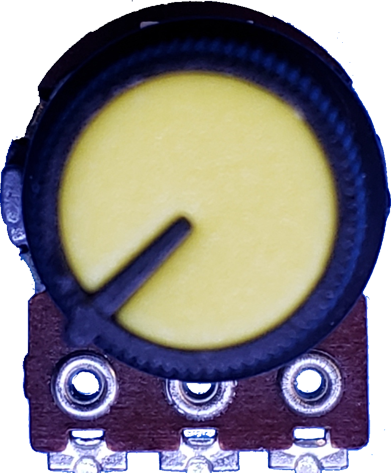
A potentiometer, often referred to as a "pot," is a three-terminal variable resistor that allows for the adjustment of voltage levels in a circuit. The smaller-sized potentiometer is compact and ideal for applications where space is limited. It is commonly used for fine-tuning signal levels, brightness, or volume in devices such as audio equipment, lighting systems, and control panels.
Explore Projects Built with Potentiometer(smaller)

Explore Projects Built with Potentiometer(smaller)
Common Applications:
- Audio equipment for volume control
- LED brightness adjustment
- Signal tuning in analog circuits
- Calibration of sensors
- User input in control systems
Technical Specifications
Below are the key technical details for a typical smaller-sized potentiometer:
| Parameter | Value |
|---|---|
| Resistance Range | 1 kΩ to 1 MΩ (varies by model) |
| Power Rating | 0.1 W to 0.5 W |
| Tolerance | ±10% |
| Operating Voltage | 0 V to 50 V |
| Operating Temperature | -10°C to +70°C |
| Adjustment Type | Rotary or linear |
| Dimensions | Compact (e.g., 10 mm diameter) |
Pin Configuration and Descriptions
The potentiometer has three pins, as described below:
| Pin Number | Name | Description |
|---|---|---|
| 1 | Terminal 1 | One end of the resistive track. Connect to the voltage source or ground. |
| 2 | Wiper | The adjustable middle pin. Outputs a variable voltage based on the knob's position. |
| 3 | Terminal 2 | The other end of the resistive track. Connect to ground or the voltage source. |
Usage Instructions
How to Use the Potentiometer in a Circuit
Connect the Terminals:
- Connect Terminal 1 to the voltage source (e.g., 5V).
- Connect Terminal 2 to ground (GND).
- Connect the Wiper (Pin 2) to the input of the circuit where you need a variable voltage.
Adjust the Resistance:
- Rotate the knob or slider to change the resistance between the wiper and the terminals.
- This adjusts the output voltage at the wiper, which can be used to control brightness, volume, or other parameters.
Test the Output:
- Use a multimeter to measure the voltage at the wiper pin to ensure it varies as expected.
Important Considerations and Best Practices
- Power Rating: Ensure the potentiometer's power rating is not exceeded to avoid damage.
- Mounting: Secure the potentiometer properly to prevent movement during operation.
- Debouncing: If used as an input device (e.g., for Arduino), consider software debouncing to handle noise.
- Avoid Overturning: Do not force the knob beyond its mechanical limits to prevent damage.
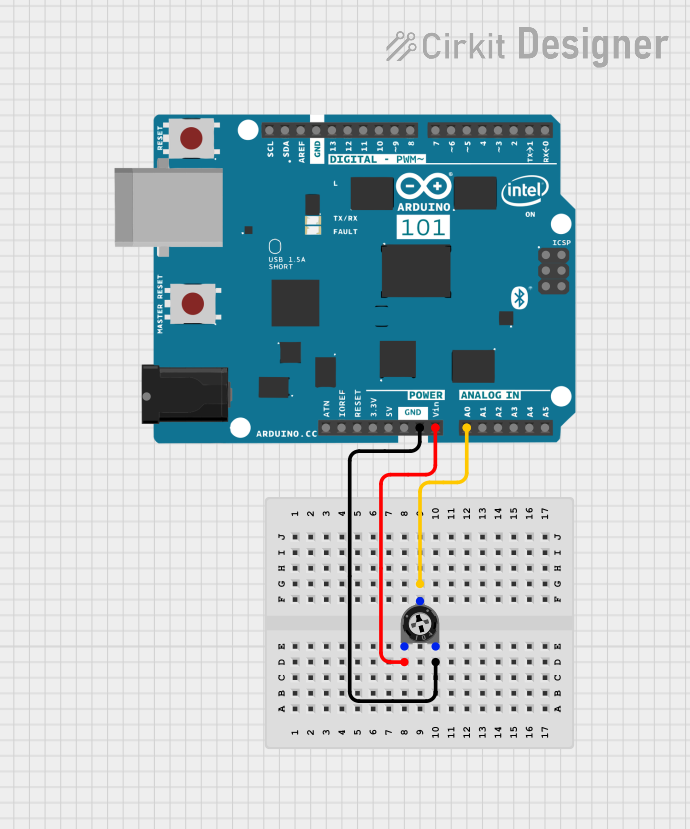
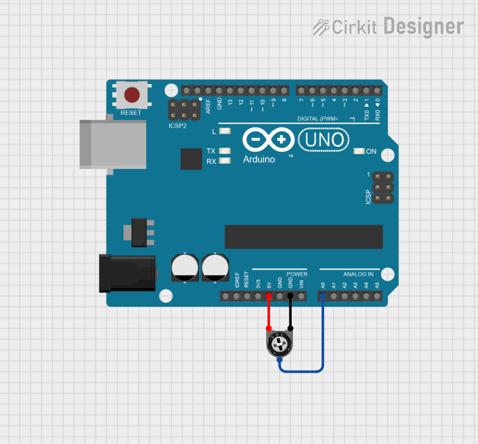
Example: Connecting to an Arduino UNO
Below is an example of how to use a smaller potentiometer with an Arduino UNO to read analog values and control an LED's brightness.
Circuit Connections:
- Connect Terminal 1 to 5V on the Arduino.
- Connect Terminal 2 to GND on the Arduino.
- Connect the Wiper (Pin 2) to an analog input pin (e.g., A0).
- Connect an LED to a PWM pin (e.g., D9) with a current-limiting resistor.
Arduino Code:
// Define pin connections
const int potPin = A0;  // Potentiometer wiper connected to analog pin A0
const int ledPin = 9;   // LED connected to digital PWM pin 9

void setup() {
  pinMode(ledPin, OUTPUT);  // Set LED pin as output
  Serial.begin(9600);       // Initialize serial communication for debugging
}

void loop() {
  int potValue = analogRead(potPin);  // Read the potentiometer value (0-1023)

  // Map the potentiometer value to a PWM range (0-255)
  int ledBrightness = map(potValue, 0, 1023, 0, 255);

  analogWrite(ledPin, ledBrightness);  // Set LED brightness

  // Print the potentiometer value for debugging
  Serial.print("Potentiometer Value: ");
  Serial.println(potValue);

  delay(100);  // Small delay for stability
}
Troubleshooting and FAQs
Common Issues and Solutions
No Output Voltage at the Wiper:
- Cause: Incorrect wiring.
- Solution: Verify that Terminal 1 and Terminal 2 are connected to the voltage source and ground, respectively.
Potentiometer Not Adjusting Properly:
- Cause: Mechanical damage or dirt inside the potentiometer.
- Solution: Clean the potentiometer or replace it if damaged.
LED Flickering When Adjusting:
- Cause: Electrical noise or poor connections.
- Solution: Ensure secure connections and consider adding a capacitor across the potentiometer terminals to reduce noise.
Arduino Not Reading Values Correctly:
- Cause: Incorrect pin configuration or faulty potentiometer.
- Solution: Double-check the wiring and test the potentiometer with a multimeter.
FAQs
Q: Can I use a smaller potentiometer for high-power applications?
A: No, smaller potentiometers typically have low power ratings (0.1 W to 0.5 W). For high-power applications, use a potentiometer with a higher power rating.
Q: How do I know the resistance value of my potentiometer?
A: The resistance value is usually printed on the body of the potentiometer (e.g., "10k" for 10 kΩ).
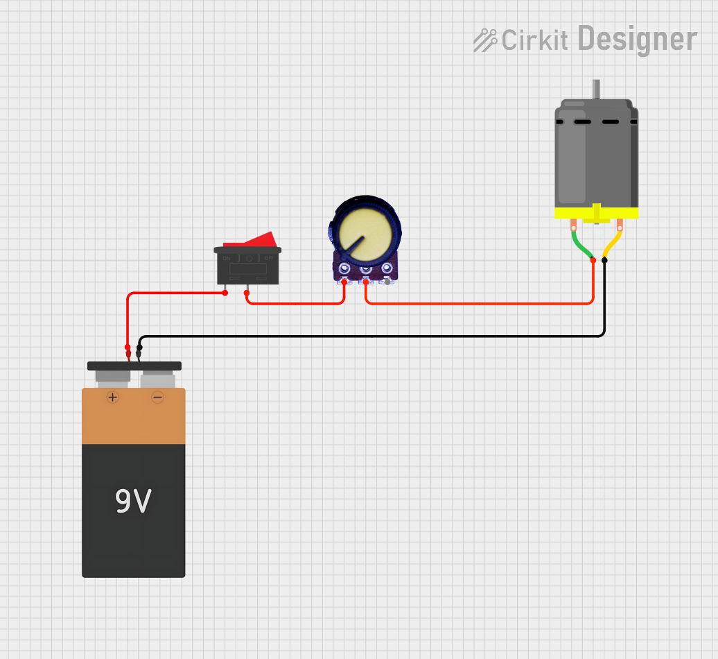
Q: Can I use a potentiometer to control a motor?
A: Directly controlling a motor with a potentiometer is not recommended due to its low power rating. Instead, use the potentiometer to control a motor driver or PWM signal.
Q: What is the lifespan of a smaller potentiometer?
A: The lifespan depends on the quality and usage but typically ranges from 10,000 to 50,000 cycles.