How to Use 1x4 Keypad: Examples, Pinouts, and Specs
1x4 Keypad Documentation
1. Introduction
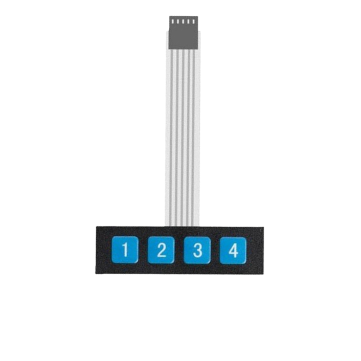
The 1x4 Keypad is a compact input device consisting of a single row of four buttons arranged in a matrix. It is commonly used in electronic projects and devices to allow users to input numeric or alphanumeric data. Each button in the keypad corresponds to a unique signal that can be read by a microcontroller or other digital circuits.
Common Applications:
- User interfaces for embedded systems
- Security systems (e.g., PIN entry)
- Menu navigation in electronic devices
- Home automation control panels
- Calculator-style input devices
The 1x4 keypad is simple to use, cost-effective, and ideal for projects requiring minimal user input.
2. Technical Specifications
The following table outlines the key technical details of the 1x4 keypad:
| Parameter | Specification |
|---|---|
| Number of Buttons | 4 |
| Button Arrangement | 1 Row x 4 Columns |
| Operating Voltage | 3.3V to 5V |
| Maximum Current | 20mA per button |
| Contact Resistance | ≤ 100Ω |
| Insulation Resistance | ≥ 100MΩ |
| Button Lifespan | ~1,000,000 presses |
| Dimensions | Varies (typically ~50mm x 20mm) |
| Connector Type | 4-pin header or solderable pads |
Pin Configuration and Descriptions
The 1x4 keypad has four pins, each corresponding to one column (button). The pins are typically labeled as C1, C2, C3, and C4. The following table describes the pin configuration:
| Pin | Label | Description |
|---|---|---|
| 1 | C1 | Column 1 (Button 1 output) |
| 2 | C2 | Column 2 (Button 2 output) |
| 3 | C3 | Column 3 (Button 3 output) |
| 4 | C4 | Column 4 (Button 4 output) |
3. Usage Instructions
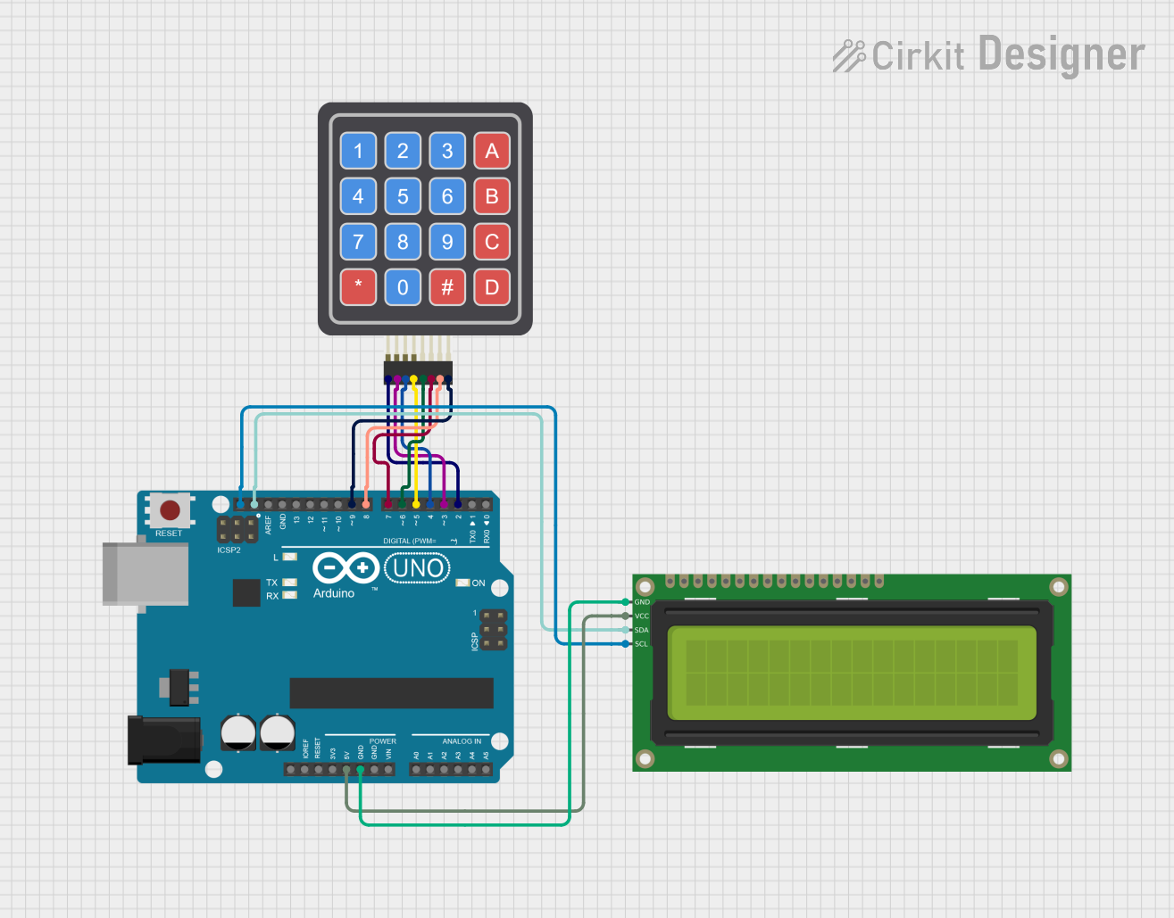
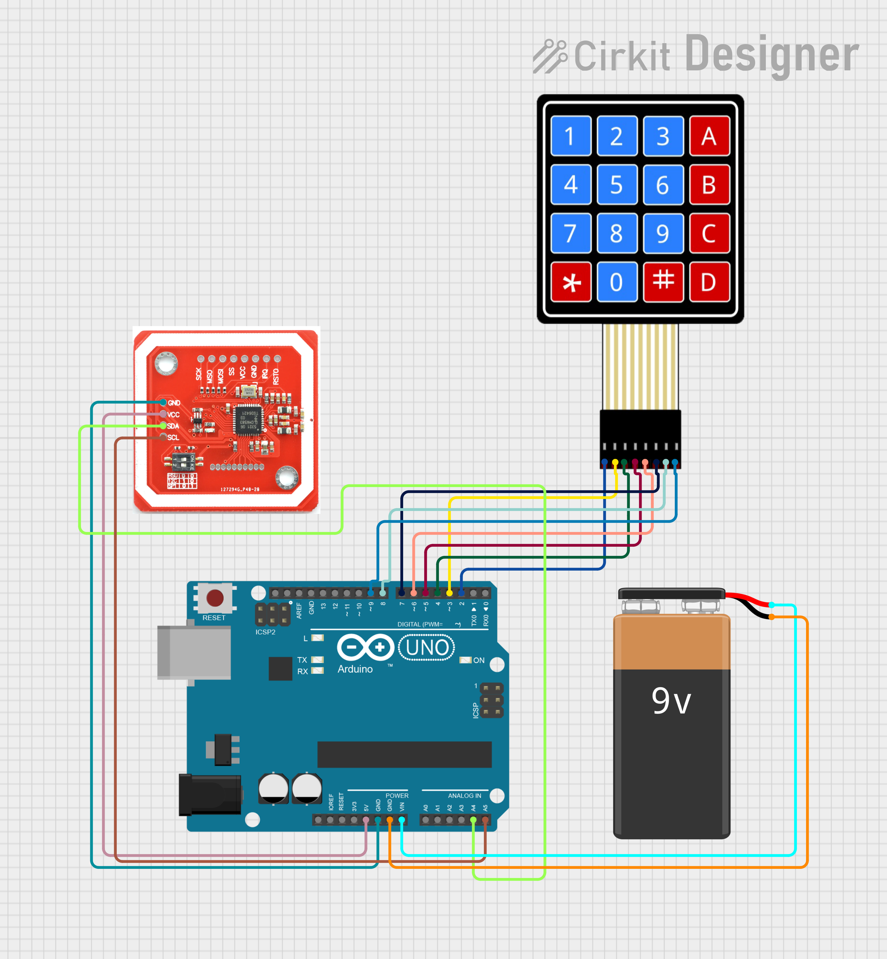
Connecting the 1x4 Keypad to a Microcontroller
To use the 1x4 keypad, connect its pins to the digital input pins of a microcontroller (e.g., Arduino UNO). Each button in the keypad is connected to a unique pin, and pressing a button will pull the corresponding pin LOW (if pull-up resistors are used).
Example Circuit:
- Connect the C1, C2, C3, and C4 pins of the keypad to digital pins on the Arduino (e.g., D2, D3, D4, D5).
- Enable internal pull-up resistors on the Arduino to detect button presses.
- Use a simple program to read the state of each pin and determine which button is pressed.
Arduino Code Example
Below is an example Arduino sketch to read button presses from a 1x4 keypad:
// Define the pins connected to the keypad
const int buttonPins[4] = {2, 3, 4, 5}; // C1, C2, C3, C4

void setup() {
  Serial.begin(9600); // Initialize serial communication for debugging

  // Set keypad pins as inputs with internal pull-up resistors
  for (int i = 0; i < 4; i++) {
    pinMode(buttonPins[i], INPUT_PULLUP);
  }
}

void loop() {
  for (int i = 0; i < 4; i++) {
    // Check if the button is pressed (LOW state)
    if (digitalRead(buttonPins[i]) == LOW) {
      Serial.print("Button ");
      Serial.print(i + 1); // Button index (1-based)
      Serial.println(" is pressed");
      delay(200); // Debounce delay
    }
  }
}
Important Considerations:
- Debouncing: Mechanical buttons can produce noise when pressed, causing multiple signals. Use a small delay (e.g.,
delay(200)) or software debouncing techniques to avoid false readings. - Pull-up Resistors: Ensure pull-up resistors are enabled (internal or external) to prevent floating pin states.
- Voltage Levels: Verify that the keypad's operating voltage matches the microcontroller's input voltage (e.g., 5V for Arduino UNO).
4. Troubleshooting and FAQs
Common Issues and Solutions
| Issue | Possible Cause | Solution |
|---|---|---|
| No response from the keypad | Loose or incorrect wiring | Check all connections and pin mappings. |
| Multiple buttons detected at once | Button bounce or floating pins | Enable pull-up resistors and debounce. |
| Incorrect button detected | Misconfigured pin assignments | Verify pin connections and code logic. |
| Buttons not working consistently | Worn-out keypad or poor contact | Replace the keypad or clean contacts. |
Frequently Asked Questions
Q1: Can I use the 1x4 keypad with a 3.3V microcontroller?
A1: Yes, the 1x4 keypad is compatible with 3.3V systems. Ensure the microcontroller's input pins can detect the LOW signal when a button is pressed.
Q2: How do I debounce the buttons in software?
A2: You can use a small delay (e.g., delay(50)) after detecting a button press or implement a more advanced debouncing algorithm using timers.
Q3: Can I connect multiple 1x4 keypads to a single microcontroller?
A3: Yes, you can connect multiple keypads by assigning each keypad to a unique set of pins. Ensure the microcontroller has enough available pins.
Q4: What happens if I press multiple buttons simultaneously?
A4: The behavior depends on your circuit and code. Typically, the microcontroller will detect the first button pressed or may register multiple signals.
5. Conclusion
The 1x4 Keypad is a versatile and easy-to-use input device for a wide range of electronic projects. Its simple design and compatibility with microcontrollers like the Arduino UNO make it an excellent choice for hobbyists and professionals alike. By following the guidelines in this documentation, you can seamlessly integrate the 1x4 keypad into your projects and create intuitive user interfaces.
Explore Projects Built with 1x4 Keypad


Explore Projects Built with 1x4 Keypad