Cirkit Designer Logo
Cirkit Designer
Your all-in-one circuit design IDE
Home / 
Component Documentation

How to Use DC-DC 12V to 3.3V 5V 12V Power Module: Examples, Pinouts, and Specs

Image of DC-DC 12V to 3.3V 5V 12V Power Module
Cirkit Designer LogoDesign with DC-DC 12V to 3.3V 5V 12V Power Module in Cirkit Designer

Introduction

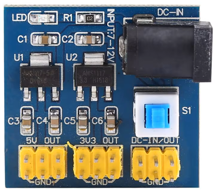
The Hailege DC-DC 12V to 3.3V 5V 12V Power Module (Manufacturer Part ID: B07Z3FPNTK) is a versatile power conversion module designed to step down a 12V input voltage to multiple output voltages, including 3.3V, 5V, and 12V. This module provides stable and efficient power for a wide range of electronic devices, making it an essential component for embedded systems, IoT devices, and prototyping projects.

Explore Projects Built with DC-DC 12V to 3.3V 5V 12V Power Module

Use Cirkit Designer to design, explore, and prototype these projects online. Some projects support real-time simulation. Click "Open Project" to start designing instantly!
DC-DC Converter and Relay Module Power Distribution System
Image of relay: A project utilizing DC-DC 12V to 3.3V 5V 12V Power Module in a practical application
This circuit consists of a DC-DC converter powering a 6-channel power module, which in turn supplies 5V to a 2-relay module. The power module distributes the converted voltage to the relay module, enabling it to control external devices.
Cirkit Designer LogoOpen Project in Cirkit Designer
Battery-Powered DC-DC Converter System for Multi-Voltage Power Distribution
Image of test 1 ih: A project utilizing DC-DC 12V to 3.3V 5V 12V Power Module in a practical application
This circuit converts a 38.5V battery output to multiple lower voltage levels using a series of DC-DC converters and a power module. It includes an emergency stop switch for safety and distributes power to various components such as a relay module, USB ports, and a bus servo adaptor.
Cirkit Designer LogoOpen Project in Cirkit Designer
Battery-Powered 18650 Li-ion Charger with USB Output and Adjustable Voltage Regulator
Image of Breadboard: A project utilizing DC-DC 12V to 3.3V 5V 12V Power Module in a practical application
This circuit is a battery management and power supply system that uses three 3.7V batteries connected to a 3S 10A Li-ion 18650 Charger Protection Board Module for balanced charging and protection. The system includes a TP4056 Battery Charging Protection Module for additional charging safety, a Step Up Boost Power Converter to regulate and boost the voltage, and a USB regulator to provide a stable 5V output, controlled by a push switch.
Cirkit Designer LogoOpen Project in Cirkit Designer
Battery-Powered Motor Control with Voltage Monitoring and LED Indicator
Image of ckt: A project utilizing DC-DC 12V to 3.3V 5V 12V Power Module in a practical application
This circuit converts AC power to DC using a bridge rectifier to drive a 12V geared motor. It also includes a TP4056 module for charging a 3.7V battery, monitored by a mini digital volt/ammeter, and an LED indicator for power status.
Cirkit Designer LogoOpen Project in Cirkit Designer

Explore Projects Built with DC-DC 12V to 3.3V 5V 12V Power Module

Use Cirkit Designer to design, explore, and prototype these projects online. Some projects support real-time simulation. Click "Open Project" to start designing instantly!
Image of relay: A project utilizing DC-DC 12V to 3.3V 5V 12V Power Module in a practical application
DC-DC Converter and Relay Module Power Distribution System
This circuit consists of a DC-DC converter powering a 6-channel power module, which in turn supplies 5V to a 2-relay module. The power module distributes the converted voltage to the relay module, enabling it to control external devices.
Cirkit Designer LogoOpen Project in Cirkit Designer
Image of test 1 ih: A project utilizing DC-DC 12V to 3.3V 5V 12V Power Module in a practical application
Battery-Powered DC-DC Converter System for Multi-Voltage Power Distribution
This circuit converts a 38.5V battery output to multiple lower voltage levels using a series of DC-DC converters and a power module. It includes an emergency stop switch for safety and distributes power to various components such as a relay module, USB ports, and a bus servo adaptor.
Cirkit Designer LogoOpen Project in Cirkit Designer
Image of Breadboard: A project utilizing DC-DC 12V to 3.3V 5V 12V Power Module in a practical application
Battery-Powered 18650 Li-ion Charger with USB Output and Adjustable Voltage Regulator
This circuit is a battery management and power supply system that uses three 3.7V batteries connected to a 3S 10A Li-ion 18650 Charger Protection Board Module for balanced charging and protection. The system includes a TP4056 Battery Charging Protection Module for additional charging safety, a Step Up Boost Power Converter to regulate and boost the voltage, and a USB regulator to provide a stable 5V output, controlled by a push switch.
Cirkit Designer LogoOpen Project in Cirkit Designer
Image of ckt: A project utilizing DC-DC 12V to 3.3V 5V 12V Power Module in a practical application
Battery-Powered Motor Control with Voltage Monitoring and LED Indicator
This circuit converts AC power to DC using a bridge rectifier to drive a 12V geared motor. It also includes a TP4056 module for charging a 3.7V battery, monitored by a mini digital volt/ammeter, and an LED indicator for power status.
Cirkit Designer LogoOpen Project in Cirkit Designer

Common Applications and Use Cases

  • Powering microcontrollers such as Arduino, ESP32, or Raspberry Pi.
  • Supplying stable voltage to sensors, relays, and other peripherals.
  • Prototyping circuits requiring multiple voltage levels.
  • Battery-powered systems where efficient voltage regulation is critical.

Technical Specifications

Below are the key technical details of the Hailege DC-DC Power Module:

Parameter Value
Input Voltage Range 12V DC
Output Voltage Options 3.3V, 5V, 12V DC
Output Current Up to 2A (varies by output voltage)
Efficiency Up to 92%
Operating Temperature -40°C to +85°C
Dimensions 45mm x 25mm x 15mm
Weight 10g

Pin Configuration and Descriptions

The module has a simple pinout for easy integration into circuits:

Pin Name Description
VIN Input voltage pin (connect to 12V DC power source).
GND Ground pin (common ground for input and output).
VOUT 3.3V 3.3V output pin for low-voltage devices.
VOUT 5V 5V output pin for standard peripherals.
VOUT 12V 12V output pin for devices requiring 12V.

Usage Instructions

How to Use the Component in a Circuit

  1. Connect the Input Voltage:

    • Attach the VIN pin to a 12V DC power source.
    • Connect the GND pin to the ground of the power source.
  2. Select the Desired Output Voltage:

    • Use the VOUT 3.3V, VOUT 5V, or VOUT 12V pins to power your devices.
    • Ensure the connected device does not exceed the maximum current rating of the module.
  3. Verify Connections:

    • Double-check all connections to avoid short circuits or incorrect wiring.
  4. Power On:

    • Turn on the 12V power source. The module will regulate the voltage and provide stable outputs.

Important Considerations and Best Practices

  • Heat Dissipation: If the module is used at high currents (close to 2A), ensure proper ventilation or add a heatsink to prevent overheating.
  • Load Compatibility: Verify that the connected devices are compatible with the output voltage and current ratings.
  • Polarity Protection: Ensure correct polarity when connecting the input voltage to avoid damaging the module.
  • Noise Filtering: For sensitive applications, consider adding capacitors at the output pins to reduce noise.

Example: Using with Arduino UNO

The 5V output of the module can be used to power an Arduino UNO. Below is an example circuit and code:

Circuit Connections

  • Connect the VIN pin of the module to a 12V DC power source.
  • Connect the GND pin of the module to the ground of the power source and Arduino.
  • Connect the VOUT 5V pin of the module to the 5V pin of the Arduino UNO.

Example Code

// Example code to blink an LED using Arduino UNO powered by the DC-DC module

const int ledPin = 13; // Built-in LED pin on Arduino UNO

void setup() {
  pinMode(ledPin, OUTPUT); // Set the LED pin as an output
}

void loop() {
  digitalWrite(ledPin, HIGH); // Turn the LED on
  delay(1000);                // Wait for 1 second
  digitalWrite(ledPin, LOW);  // Turn the LED off
  delay(1000);                // Wait for 1 second
}

Troubleshooting and FAQs

Common Issues Users Might Face

  1. No Output Voltage:

    • Cause: Incorrect wiring or insufficient input voltage.
    • Solution: Verify the input voltage is 12V and check all connections.
  2. Overheating:

    • Cause: Excessive current draw or poor ventilation.
    • Solution: Reduce the load current or add a heatsink to the module.
  3. Voltage Instability:

    • Cause: Noise or insufficient filtering.
    • Solution: Add capacitors (e.g., 10µF and 0.1µF) across the output pins.
  4. Device Not Powering On:

    • Cause: Incorrect output voltage selection.
    • Solution: Ensure the device is connected to the correct output pin (3.3V, 5V, or 12V).

Solutions and Tips for Troubleshooting

  • Use a multimeter to measure the input and output voltages for debugging.
  • Avoid exceeding the maximum current rating to prevent damage to the module.
  • If the module fails to operate, inspect for physical damage or burnt components.

By following this documentation, users can effectively integrate the Hailege DC-DC 12V to 3.3V 5V 12V Power Module into their projects and ensure reliable performance.