Cirkit Designer Logo
Cirkit Designer
Your all-in-one circuit design IDE
Home / 
Component Documentation

How to Use Adafruit TPL5111 Reset Enable Timer: Examples, Pinouts, and Specs

Image of Adafruit TPL5111 Reset Enable Timer
Cirkit Designer LogoDesign with Adafruit TPL5111 Reset Enable Timer in Cirkit Designer

Introduction

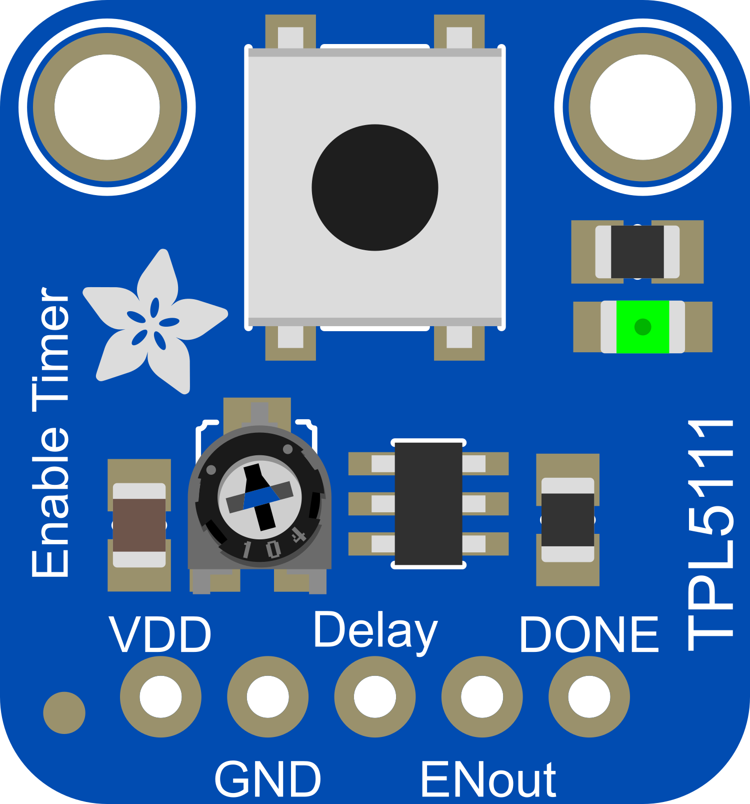
The Adafruit TPL5111 Reset Enable Timer is a breakout board designed to facilitate timed power cycling or enable/disable operations for electronic projects. This component is particularly useful for battery-powered applications where power conservation is crucial. By allowing scheduled wake-ups or resets, the TPL5111 helps in extending battery life and reducing power consumption.

Explore Projects Built with Adafruit TPL5111 Reset Enable Timer

Use Cirkit Designer to design, explore, and prototype these projects online. Some projects support real-time simulation. Click "Open Project" to start designing instantly!
Arduino Nano Controlled Timer with Relay, Buzzer, and I2C LCD Display
Image of Automatic solar light with timer: A project utilizing Adafruit TPL5111 Reset Enable Timer in a practical application
This circuit is designed as a configurable timer system controlled by an Arduino Nano, which drives a relay to switch a 240V bulb on and off. The timer duration can be adjusted using pushbuttons, and the remaining time is displayed on an I2C LCD screen. When the timer expires, a buzzer sounds, and the relay turns off the bulb, indicating the end of the timing period.
Cirkit Designer LogoOpen Project in Cirkit Designer
Arduino UNO Countdown Timer with 7-Segment Display and Alert System
Image of Adjustable Timer 7 segment display: A project utilizing Adafruit TPL5111 Reset Enable Timer in a practical application
This circuit functions as a configurable timer with visual and audible alerts. An Arduino UNO microcontroller reads input from a 4-position DIP switch to set the timer duration, displays the countdown on a 7-segment serial display, and uses a tactile button to start the countdown. When the timer reaches zero, it activates a red LED and a buzzer to signal the end of the timing period.
Cirkit Designer LogoOpen Project in Cirkit Designer
Arduino UNO-Based Countdown Timer with LCD Display and Relay Control
Image of Student01: A project utilizing Adafruit TPL5111 Reset Enable Timer in a practical application
This circuit is a countdown timer system controlled by an Arduino UNO, featuring multiple pushbuttons for time adjustment and a relay for triggering an external device. The LCD screen displays the countdown, and the relay activates when the timer reaches zero. The system is powered by a 7.4V battery and a 220V power source.
Cirkit Designer LogoOpen Project in Cirkit Designer
555 Timer-Based LED Blinker with Pushbutton Control
Image of counter: A project utilizing Adafruit TPL5111 Reset Enable Timer in a practical application
This circuit is a simple timer using a 555 timer IC configured in monostable mode. It includes a pushbutton to trigger the timer, resistors and a capacitor to set the timing interval, and an LED to indicate the output state.
Cirkit Designer LogoOpen Project in Cirkit Designer

Explore Projects Built with Adafruit TPL5111 Reset Enable Timer

Use Cirkit Designer to design, explore, and prototype these projects online. Some projects support real-time simulation. Click "Open Project" to start designing instantly!
Image of Automatic solar light with timer: A project utilizing Adafruit TPL5111 Reset Enable Timer in a practical application
Arduino Nano Controlled Timer with Relay, Buzzer, and I2C LCD Display
This circuit is designed as a configurable timer system controlled by an Arduino Nano, which drives a relay to switch a 240V bulb on and off. The timer duration can be adjusted using pushbuttons, and the remaining time is displayed on an I2C LCD screen. When the timer expires, a buzzer sounds, and the relay turns off the bulb, indicating the end of the timing period.
Cirkit Designer LogoOpen Project in Cirkit Designer
Image of Adjustable Timer 7 segment display: A project utilizing Adafruit TPL5111 Reset Enable Timer in a practical application
Arduino UNO Countdown Timer with 7-Segment Display and Alert System
This circuit functions as a configurable timer with visual and audible alerts. An Arduino UNO microcontroller reads input from a 4-position DIP switch to set the timer duration, displays the countdown on a 7-segment serial display, and uses a tactile button to start the countdown. When the timer reaches zero, it activates a red LED and a buzzer to signal the end of the timing period.
Cirkit Designer LogoOpen Project in Cirkit Designer
Image of Student01: A project utilizing Adafruit TPL5111 Reset Enable Timer in a practical application
Arduino UNO-Based Countdown Timer with LCD Display and Relay Control
This circuit is a countdown timer system controlled by an Arduino UNO, featuring multiple pushbuttons for time adjustment and a relay for triggering an external device. The LCD screen displays the countdown, and the relay activates when the timer reaches zero. The system is powered by a 7.4V battery and a 220V power source.
Cirkit Designer LogoOpen Project in Cirkit Designer
Image of counter: A project utilizing Adafruit TPL5111 Reset Enable Timer in a practical application
555 Timer-Based LED Blinker with Pushbutton Control
This circuit is a simple timer using a 555 timer IC configured in monostable mode. It includes a pushbutton to trigger the timer, resistors and a capacitor to set the timing interval, and an LED to indicate the output state.
Cirkit Designer LogoOpen Project in Cirkit Designer

Common Applications and Use Cases

  • Power cycling microcontrollers or other electronics at set intervals
  • Enabling or disabling peripherals to conserve power
  • Scheduled wake-ups for data logging or sensor reading tasks
  • IoT devices requiring periodic operation

Technical Specifications

Key Technical Details

  • Supply Voltage (VDD): 1.8V to 5.5V
  • Maximum Time Delay: 2 hours
  • Minimum Time Delay: 100 ms
  • Operating Current (VDD = 3.3V): 20 nA (typical)
  • Maximum Allowable Current on DRV Pin: 20 mA

Pin Configuration and Descriptions

Pin Number Name Description
1 GND Ground connection
2 VDD Supply voltage input (1.8V to 5.5V)
3 DELAY Delay setting input (connect to resistor for timing)
4 DRV Drive output (connect to reset or enable pin of target device)
5 DONE Signal input to indicate task completion and reset timer

Usage Instructions

How to Use the Component in a Circuit

  1. Connect Power: Attach VDD to your power supply (1.8V to 5.5V) and GND to the ground.
  2. Set Delay: Connect a resistor between the DELAY pin and ground to set the desired delay interval.
  3. Connect Drive Output: Attach the DRV pin to the reset or enable pin of the device you wish to control.
  4. Signal Completion: Connect the DONE pin to a GPIO pin on your microcontroller to signal task completion.

Important Considerations and Best Practices

  • Ensure that the supply voltage does not exceed 5.5V to prevent damage to the TPL5111.
  • Select a resistor for the DELAY pin based on the desired time interval using the formula provided in the TPL5111 datasheet.
  • Avoid drawing more than 20 mA from the DRV pin.
  • Use a pull-up resistor on the DONE pin if your microcontroller does not have an internal pull-up.

Example Code for Arduino UNO

// Example code to use Adafruit TPL5111 with Arduino UNO

const int donePin = 2; // Connect this to the DONE pin on the TPL5111

void setup() {
  pinMode(donePin, OUTPUT);
  digitalWrite(donePin, LOW);
}

void loop() {
  // Perform your task here
  
  // Signal the TPL5111 that the task is done
  digitalWrite(donePin, HIGH);
  delay(100); // Wait for 100ms to ensure the signal is registered
  digitalWrite(donePin, LOW);
  
  // Enter sleep mode or perform low-power operations until the TPL5111 resets the system
}

Troubleshooting and FAQs

Common Issues Users Might Face

  • TPL5111 not resetting the device: Ensure that the DELAY pin is correctly configured with the appropriate resistor value.
  • Device resets too quickly or too slowly: Double-check the resistor value connected to the DELAY pin and adjust it according to the datasheet formula.
  • DRV pin not providing enough current: Verify that the current requirement of the target device's reset or enable pin does not exceed 20 mA.

Solutions and Tips for Troubleshooting

  • If the timer is not operating as expected, recheck all connections, especially the DELAY resistor and the DONE pin wiring.
  • Use a multimeter to measure the voltage at the VDD pin to ensure that the TPL5111 is powered correctly.
  • For issues related to timing accuracy, consider environmental factors such as temperature that might affect the resistor value.

FAQs

Q: Can I use the TPL5111 for intervals longer than 2 hours? A: No, the maximum delay interval for the TPL5111 is 2 hours. For longer intervals, consider using a different timer solution or an external microcontroller with sleep functionality.

Q: How do I calculate the resistor value for a specific delay? A: Use the formula provided in the TPL5111 datasheet, which relates the resistor value to the desired delay time.

Q: Is it possible to change the delay interval dynamically? A: Yes, you can use a digital potentiometer or a DAC to dynamically adjust the voltage at the DELAY pin, thereby changing the delay interval.

This documentation provides a comprehensive guide to using the Adafruit TPL5111 Reset Enable Timer in your projects. For further information, consult the official datasheet and Adafruit's resources.