How to Use STP75NF75: Examples, Pinouts, and Specs
Introduction
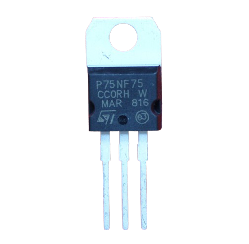
The STP75NF75 is an N-channel MOSFET transistor designed for high current and high voltage applications. It is widely used in power management, motor control circuits, and other applications requiring efficient switching and amplification. This component is known for its low on-resistance and high-speed switching capabilities, making it ideal for demanding electronic projects.
Explore Projects Built with STP75NF75


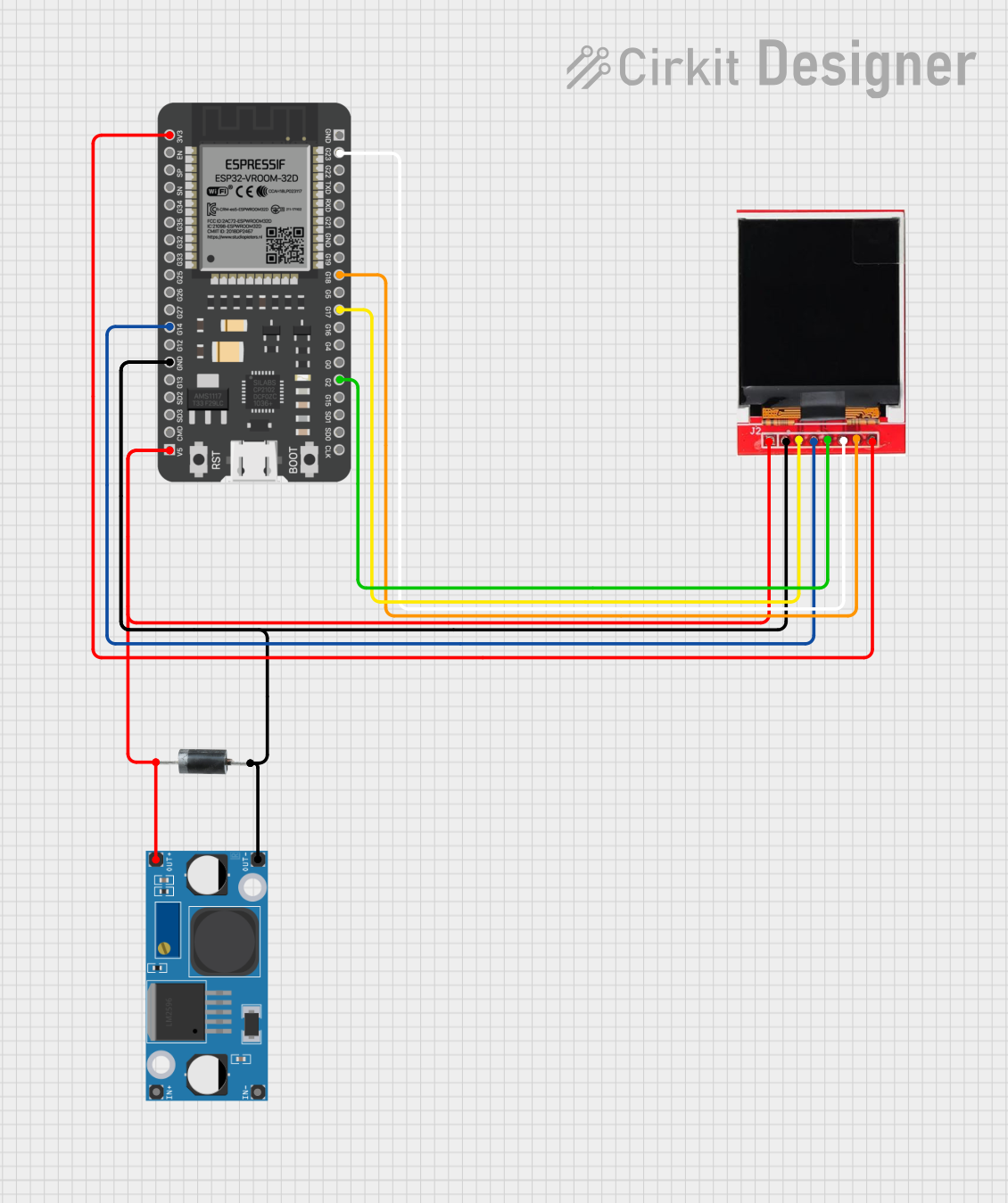
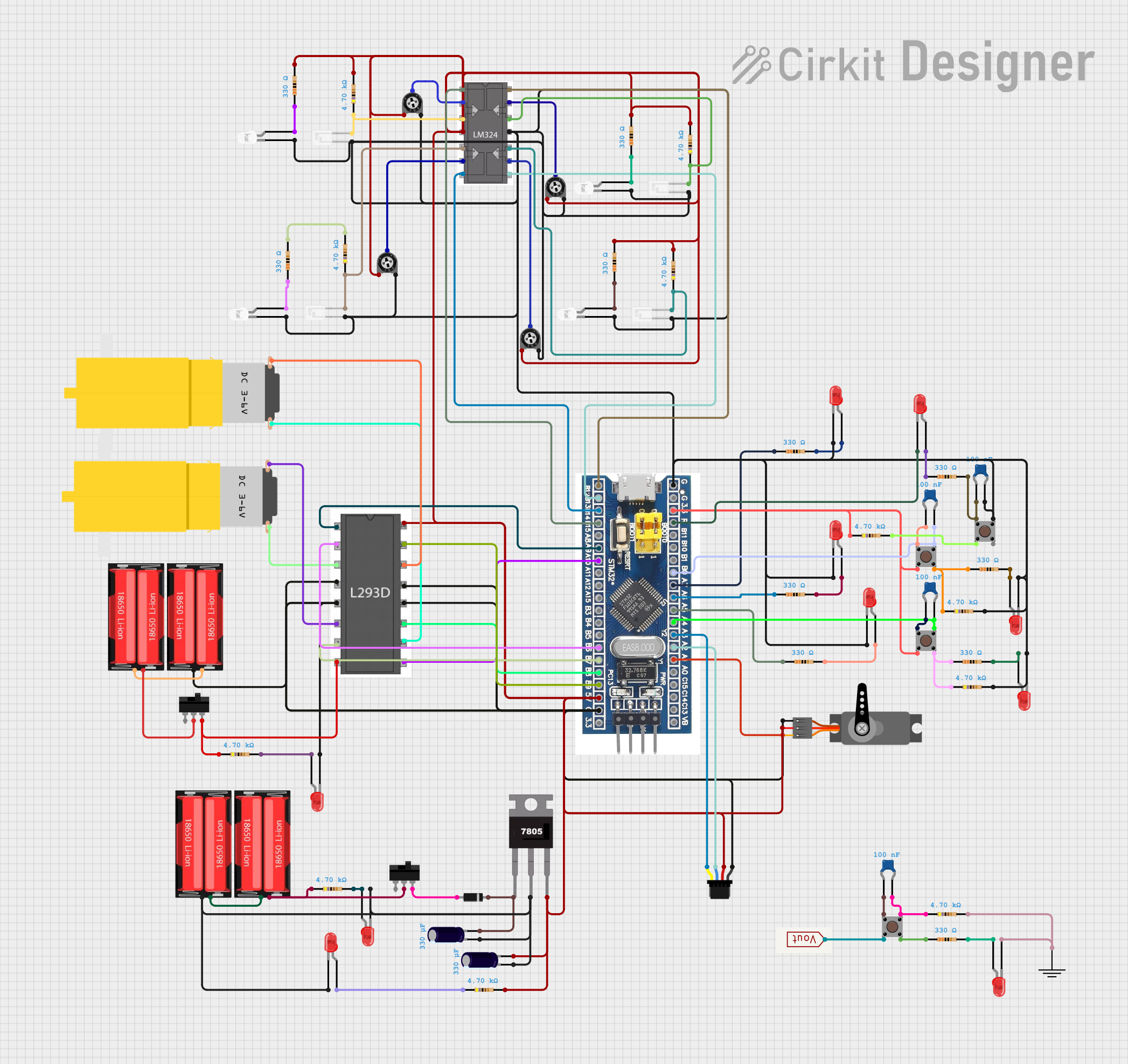
Explore Projects Built with STP75NF75
Technical Specifications
Key Technical Details
| Parameter | Value |
|---|---|
| Drain-Source Voltage (VDS) | 75V |
| Gate-Source Voltage (VGS) | ±20V |
| Continuous Drain Current (ID) | 80A |
| Pulsed Drain Current (IDM) | 320A |
| Power Dissipation (PD) | 300W |
| RDS(on) (Max) | 0.009 Ω |
| Gate Charge (Qg) | 160 nC |
| Operating Temperature Range | -55°C to 175°C |
| Package Type | TO-220 |
Pin Configuration and Descriptions
| Pin Number | Pin Name | Description |
|---|---|---|
| 1 | Gate | Controls the MOSFET switching |
| 2 | Drain | Current flows from drain to source |
| 3 | Source | Current flows to ground or load |
| Tab | Drain | Connected to the drain internally |
Usage Instructions
How to Use the Component in a Circuit
- Identify the Pins: Ensure you correctly identify the gate, drain, and source pins.
- Connect the Gate: Connect the gate pin to the control signal, typically from a microcontroller or a gate driver circuit.
- Connect the Drain: Connect the drain pin to the load you wish to control.
- Connect the Source: Connect the source pin to ground or the negative terminal of your power supply.
- Gate Resistor: Use a gate resistor (typically 10-100 ohms) to limit the inrush current to the gate.
- Flyback Diode: If driving inductive loads (e.g., motors), use a flyback diode across the load to protect the MOSFET from voltage spikes.
Important Considerations and Best Practices
- Heat Dissipation: Ensure adequate heat sinking to manage power dissipation and prevent thermal runaway.
- Gate Drive Voltage: Ensure the gate drive voltage is sufficient to fully turn on the MOSFET (typically 10V for full enhancement).
- Avoid Overvoltage: Do not exceed the maximum VDS and VGS ratings to prevent damage.
- Switching Speed: Consider the switching speed and gate charge when designing high-frequency circuits.
Example Circuit with Arduino UNO
/*
 * Example code to control an STP75NF75 MOSFET with an Arduino UNO.
 * This example turns on and off an LED connected to the MOSFET.
 */

const int gatePin = 9; // Pin connected to the MOSFET gate

void setup() {
  pinMode(gatePin, OUTPUT); // Set the gate pin as an output
}

void loop() {
  digitalWrite(gatePin, HIGH); // Turn on the MOSFET
  delay(1000); // Wait for 1 second
  digitalWrite(gatePin, LOW); // Turn off the MOSFET
  delay(1000); // Wait for 1 second
}
Troubleshooting and FAQs
Common Issues Users Might Face
MOSFET Not Turning On/Off Properly:
- Solution: Ensure the gate voltage is sufficient to fully enhance the MOSFET. Check the gate resistor value and connections.
Excessive Heating:
- Solution: Verify the heat sink is adequate. Check for excessive current through the MOSFET and ensure proper ventilation.
Unexpected Switching Behavior:
- Solution: Check for noise on the gate signal. Use a gate driver if necessary to provide a clean and strong gate signal.
MOSFET Damage:
- Solution: Ensure the voltage and current ratings are not exceeded. Use protective components like flyback diodes for inductive loads.
FAQs
Q1: Can I use the STP75NF75 for low voltage applications?
- A1: Yes, the STP75NF75 can be used for low voltage applications, but ensure the gate drive voltage is sufficient to fully turn on the MOSFET.
Q2: How do I calculate the required heat sink?
- A2: Calculate the power dissipation using P = ID² * RDS(on). Use this value to select a heat sink with an appropriate thermal resistance.
Q3: What is the maximum switching frequency for the STP75NF75?
- A3: The maximum switching frequency depends on the gate charge and the drive circuit. Typically, it can handle frequencies up to several hundred kHz with proper gate drive.
Q4: Can I parallel multiple STP75NF75 MOSFETs?
- A4: Yes, you can parallel multiple MOSFETs, but ensure they are well-matched and use proper gate resistors to balance the current.
This documentation provides a comprehensive guide to using the STP75NF75 N-channel MOSFET transistor. Whether you are a beginner or an experienced user, following these guidelines will help you effectively integrate this component into your electronic projects.