How to Use DX LR 02 (LoRa Transceiver Module): Examples, Pinouts, and Specs
Introduction
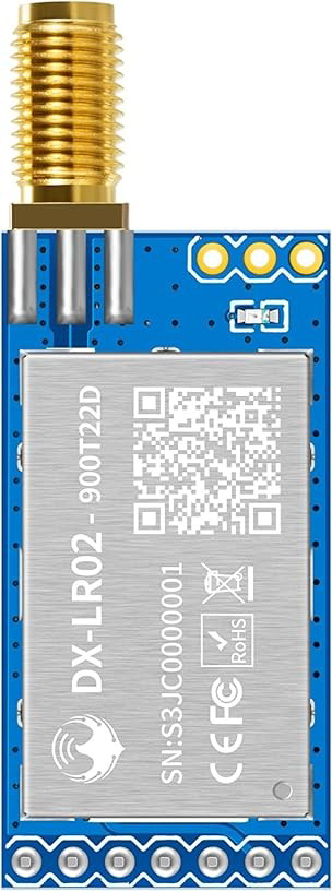
The DX LR 02 is a low-power, long-range transceiver module that leverages LoRa (Long Range) technology for wireless communication. It is designed to provide robust and efficient data transmission over extended distances, making it an excellent choice for Internet of Things (IoT) applications. The module operates in the unlicensed ISM (Industrial, Scientific, and Medical) frequency bands, ensuring compliance with global standards.
Explore Projects Built with DX LR 02 (LoRa Transceiver Module)


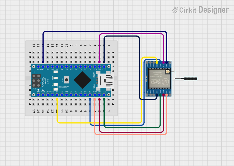
Explore Projects Built with DX LR 02 (LoRa Transceiver Module)
Common Applications and Use Cases
- Smart agriculture (e.g., soil moisture monitoring, weather stations)
- Industrial automation and monitoring
- Smart cities (e.g., parking sensors, street lighting control)
- Asset tracking and logistics
- Environmental monitoring (e.g., air quality sensors)
- Home automation and security systems
Technical Specifications
The DX LR 02 module is designed to meet the needs of low-power, long-range communication systems. Below are its key technical details:
General Specifications
| Parameter | Value |
|---|---|
| Frequency Range | 868 MHz (EU) / 915 MHz (US) |
| Modulation Technique | LoRa (CSS - Chirp Spread Spectrum) |
| Output Power | Up to +20 dBm |
| Sensitivity | -137 dBm |
| Data Rate | 0.3 kbps to 37.5 kbps |
| Supply Voltage | 1.8V to 3.7V |
| Current Consumption | 10 mA (Rx), 120 mA (Tx @ +20 dBm) |
| Communication Interface | SPI |
| Operating Temperature | -40°C to +85°C |
| Dimensions | 18 mm x 20 mm x 3 mm |
Pin Configuration and Descriptions
The DX LR 02 module has 8 pins, as described in the table below:
| Pin Number | Pin Name | Description |
|---|---|---|
| 1 | GND | Ground connection |
| 2 | VCC | Power supply (1.8V to 3.7V) |
| 3 | SCK | SPI clock input |
| 4 | MISO | SPI data output |
| 5 | MOSI | SPI data input |
| 6 | NSS | SPI chip select (active low) |
| 7 | DIO0 | Digital I/O pin 0 (used for interrupts) |
| 8 | RESET | Module reset (active low) |
Usage Instructions
How to Use the DX LR 02 in a Circuit
- Power Supply: Connect the VCC pin to a regulated power source (1.8V to 3.7V) and the GND pin to the ground.
- SPI Communication: Connect the SCK, MISO, MOSI, and NSS pins to the corresponding SPI pins on your microcontroller.
- Interrupt Handling: Use the DIO0 pin to handle interrupts for events like packet reception or transmission completion.
- Reset: Connect the RESET pin to a GPIO pin on your microcontroller for resetting the module when needed.
Important Considerations and Best Practices
- Antenna Design: Ensure a proper antenna is connected to the module for optimal range and performance.
- Power Supply Filtering: Use decoupling capacitors (e.g., 0.1 µF and 10 µF) near the VCC pin to reduce noise.
- SPI Speed: Configure the SPI clock speed to match the module's requirements (typically up to 10 MHz).
- Regulatory Compliance: Operate the module within the allowed frequency bands and power levels for your region.
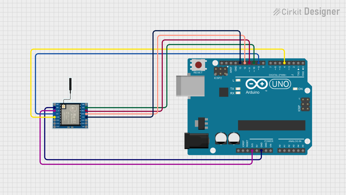
Example Code for Arduino UNO
Below is an example of how to interface the DX LR 02 with an Arduino UNO using the SPI library:
#include <SPI.h>

// Pin definitions for the DX LR 02 module
#define NSS_PIN 10    // SPI chip select pin
#define RESET_PIN 9   // Reset pin
#define DIO0_PIN 2    // Interrupt pin

void setup() {
  // Initialize serial communication for debugging
  Serial.begin(9600);
  while (!Serial);

  // Initialize SPI
  SPI.begin();
  pinMode(NSS_PIN, OUTPUT);
  pinMode(RESET_PIN, OUTPUT);
  pinMode(DIO0_PIN, INPUT);

  // Reset the module
  digitalWrite(RESET_PIN, LOW);
  delay(10);  // Hold reset low for 10 ms
  digitalWrite(RESET_PIN, HIGH);

  Serial.println("DX LR 02 initialized.");
}

void loop() {
  // Example: Send a dummy command over SPI
  digitalWrite(NSS_PIN, LOW);  // Select the module
  SPI.transfer(0x01);          // Send a dummy command
  digitalWrite(NSS_PIN, HIGH); // Deselect the module

  delay(1000);  // Wait for 1 second
}
Troubleshooting and FAQs
Common Issues and Solutions
No Communication with the Module
- Solution: Verify the SPI connections and ensure the NSS, SCK, MISO, and MOSI pins are correctly wired.
- Tip: Check the SPI clock speed and ensure it is within the module's supported range.
Poor Range or Signal Quality
- Solution: Ensure the antenna is properly connected and positioned. Use a high-quality antenna designed for the operating frequency.
- Tip: Avoid placing the module near sources of interference, such as high-frequency switching power supplies.
Module Not Responding After Power-Up
- Solution: Check the power supply voltage and ensure it is within the specified range (1.8V to 3.7V).
- Tip: Perform a hardware reset by toggling the RESET pin.
Intermittent Data Loss
- Solution: Verify the SPI communication and ensure proper interrupt handling on the DIO0 pin.
- Tip: Use error-checking mechanisms like CRC to ensure data integrity.
FAQs
Q: Can the DX LR 02 module be used for bidirectional communication?
A: Yes, the module supports both transmission and reception, making it suitable for bidirectional communication.
Q: What is the maximum range of the DX LR 02?
A: The range depends on environmental factors, but it can achieve up to 10 km in open areas with a clear line of sight.
Q: Is the module compatible with 5V microcontrollers?
A: The module operates at 1.8V to 3.7V. Use a level shifter to interface with 5V microcontrollers.
Q: Does the module support encryption?
A: Yes, the DX LR 02 supports AES-128 encryption for secure communication.