How to Use Arduino Board Ethernet: Examples, Pinouts, and Specs
Introduction
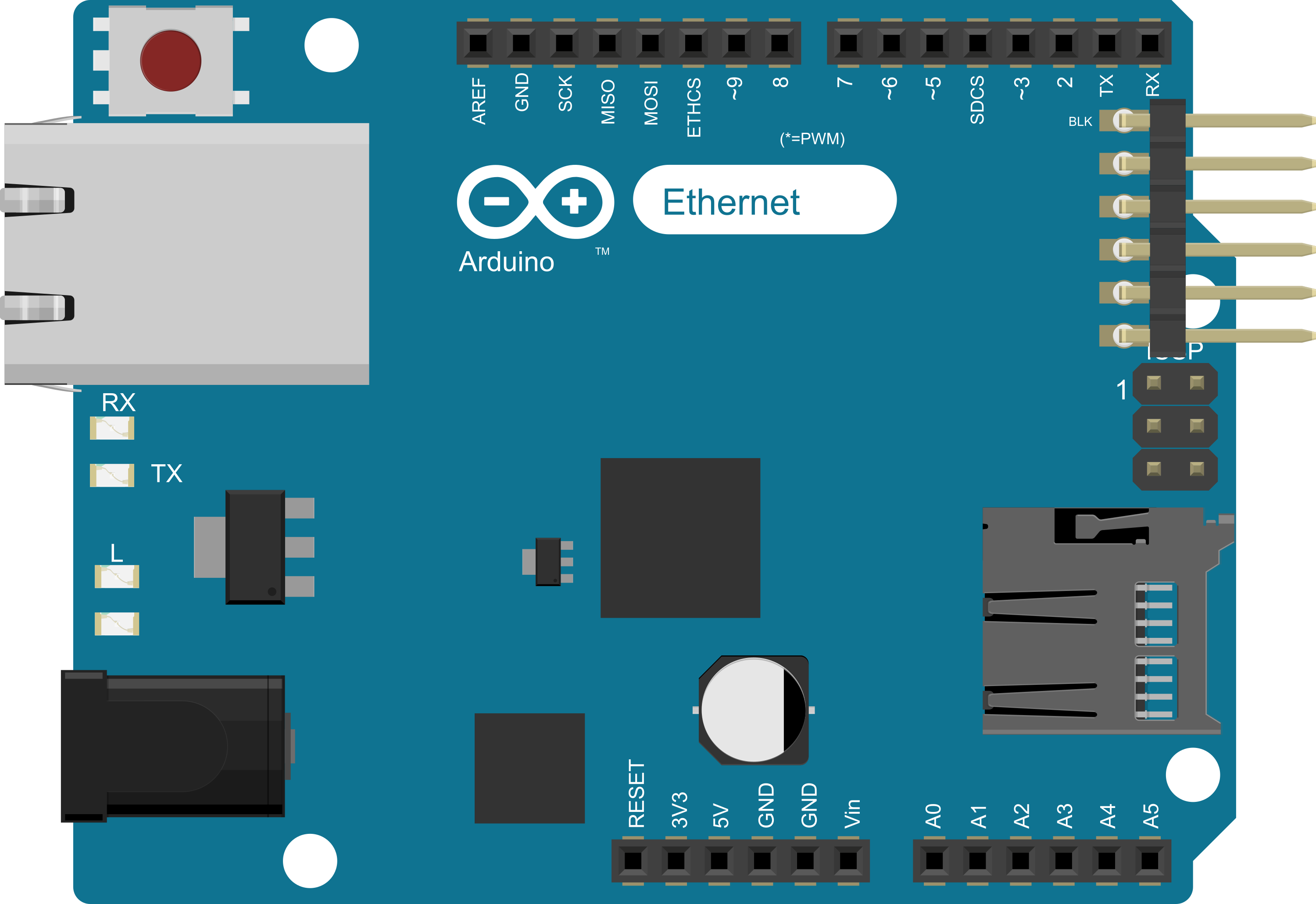
The Arduino Ethernet Board is a microcontroller board based on the ATmega328P, which is the same microcontroller used in the popular Arduino Uno. This board is specifically designed to provide an easy way to integrate Ethernet connectivity into your projects. It comes with a built-in Ethernet controller, allowing for networked applications. Common use cases include creating web servers, network sensors, and devices that can be controlled remotely over a network.
Explore Projects Built with Arduino Board Ethernet
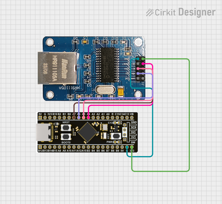

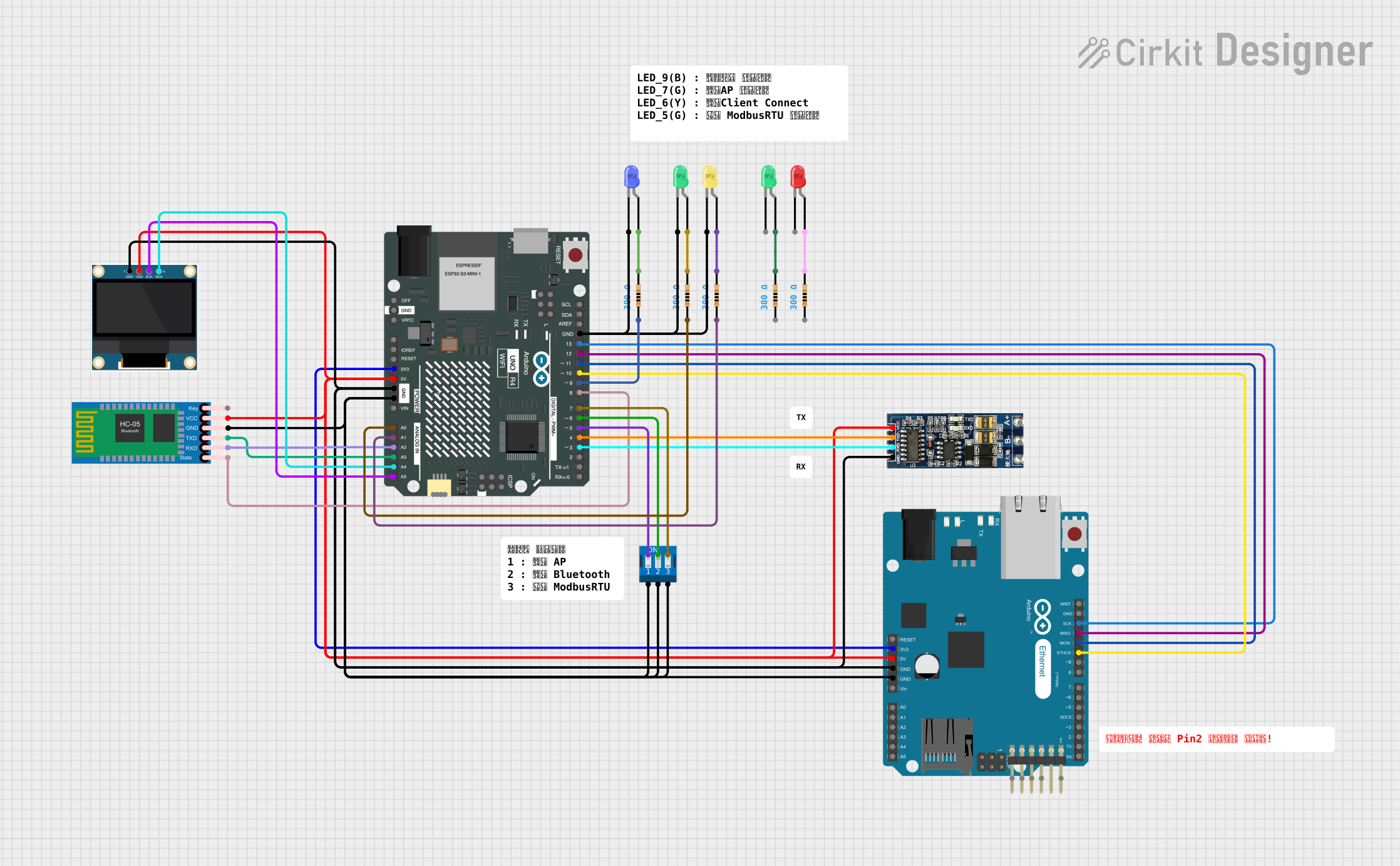
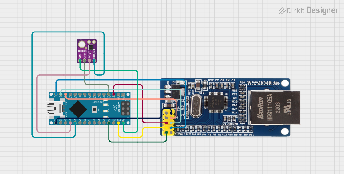
Explore Projects Built with Arduino Board Ethernet
Technical Specifications
Key Technical Details
- Microcontroller: ATmega328P
- Operating Voltage: 5V
- Input Voltage (recommended): 7-12V
- Input Voltage (limit): 6-20V
- Digital I/O Pins: 14 (of which 4 provide PWM output)
- Analog Input Pins: 6
- DC Current per I/O Pin: 40 mA
- DC Current for 3.3V Pin: 50 mA
- Flash Memory: 32 KB (ATmega328P) of which 0.5 KB used by bootloader
- SRAM: 2 KB (ATmega328P)
- EEPROM: 1 KB (ATmega328P)
- Clock Speed: 16 MHz
- Ethernet Controller: WizNet W5100 TCP/IP Embedded Ethernet Controller
- Power-over-Ethernet (PoE) Module: Compatible (module sold separately)
Pin Configuration and Descriptions
| Pin Number | Function | Description |
|---|---|---|
| 1 | TX (D1) | Digital pin for UART transmit |
| 2 | RX (D0) | Digital pin for UART receive |
| 3-5 | D2-D4 | General purpose digital I/O pins |
| 6 | D5 (PWM) | Digital pin with PWM output capability |
| 7-12 | D6-D11 | General purpose digital I/O pins |
| 13 | D12 (PWM) | Digital pin with PWM output capability |
| 14 | D13 (LED) | Built-in LED, also used for SPI SCK |
| A0-A5 | Analog In | Analog input pins |
| AREF | Analog Ref | Reference voltage for the analog inputs |
| GND | Ground | Ground pins |
| RST | Reset | Used to reset the microcontroller |
| 3V3 | 3.3V Supply | 3.3V output from the onboard voltage regulator |
| 5V | 5V Supply | 5V output from the onboard voltage regulator |
| VIN | Voltage In | Input voltage to the Arduino board when using an external power source |
Usage Instructions
Integrating the Arduino Ethernet Board into a Circuit
Powering the Board:
- You can power the Arduino Ethernet Board via the USB connection or with an external power supply. The power source is selected automatically.
- The recommended voltage for the external power supply is 7-12V.
Connecting to a Network:
- Use a standard Ethernet cable to connect the RJ45 port to your network switch or router.
- Ensure that the network settings in your code match your network configuration.
Programming the Board:
- The board can be programmed with the Arduino Software (IDE). Select "Arduino Ethernet" from the Tools > Board menu.
- Use the included USB cable to connect the board to your computer for programming.
Important Considerations and Best Practices
- Static Protection: The Ethernet port can be sensitive to static discharge. Handle the board with care, especially in dry environments.
- Isolation: When using PoE, ensure that the board is isolated from conductive surfaces to prevent shorts.
- Heat Dissipation: If the board is enclosed, make sure there is adequate ventilation to dissipate heat.
Example Code for Arduino UNO
Here is a simple example of how to use the Arduino Ethernet Board to create a web server that turns on and off an LED connected to pin 4:
#include <SPI.h>
#include <Ethernet.h>

// MAC address for the Ethernet shield
byte mac[] = { 0xDE, 0xAD, 0xBE, 0xEF, 0xFE, 0xED };
// IP address for the Ethernet shield
IPAddress ip(192, 168, 1, 177);
// Initialize the Ethernet server library
EthernetServer server(80);

void setup() {
  pinMode(4, OUTPUT);      // Set the LED pin as an output
  Ethernet.begin(mac, ip); // Start the Ethernet connection and the server
  server.begin();
}

void loop() {
  EthernetClient client = server.available(); // Listen for incoming clients

  if (client) { // If a new client connects,
    boolean currentLineIsBlank = true;
    while (client.connected()) {
      if (client.available()) { // If there's bytes to read from the client,
        char c = client.read(); // Read a byte
        // If the byte is a newline character and the line is blank,
        // the HTTP request has ended, so you can send a reply
        if (c == '\n' && currentLineIsBlank) {
          // Send a standard HTTP response header
          client.println("HTTP/1.1 200 OK");
          client.println("Content-Type: text/html");
          client.println("Connection: close");
          client.println();
          // Web page content
          client.println("<!DOCTYPE HTML>");
          client.println("<html>");
          // Add a link that toggles the LED on pin 4
          client.println("<a href=\"/H\">Turn On LED</a><br>");
          client.println("<a href=\"/L\">Turn Off LED</a>");
          client.println("</html>");
          break;
        }
        if (c == '\n') {
          // If you got a newline, then the line is over
          currentLineIsBlank = true;
        } else if (c != '\r') {
          // If you got anything else, the line is not blank
          currentLineIsBlank = false;
        }
      }
    }
    // Give the web browser time to receive the data
    delay(1);
    // Close the connection
    client.stop();
  }
}
Troubleshooting and FAQs
Common Issues
Board Not Connecting to Network:
- Ensure that the Ethernet cable is properly connected and that the router or switch is functioning.
- Check that the MAC and IP addresses in your code match your network's requirements.
Cannot Upload Sketches:
- Verify that the correct board is selected in the Arduino IDE.
- Ensure that the correct driver is installed for the board.
LED Not Responding to Web Commands:
- Check the wiring of the LED and ensure it is connected to the correct pin.
- Verify that the server code is correctly parsing the HTTP request.
Solutions and Tips for Troubleshooting
Reset the Board:
- Press the reset button on the board to restart the microcontroller.
Check Network Configuration:
- Use a network scanner to ensure that the board is on the network and that the IP address is correct.
Review Code:
- Double-check the code for any syntax or logical errors.
Consult the Community:
- The Arduino community is a great resource for troubleshooting. Consider posting on forums or searching for similar issues.
For further assistance, refer to the official Arduino Ethernet Board documentation and community forums.