How to Use 테무 릴레이 4개 버튼: Examples, Pinouts, and Specs
Introduction
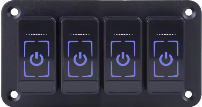
The 테무 릴레이 4개 버튼 is a versatile 4-channel relay module designed for controlling high-power devices using low-power control signals. Manufactured by 테무, this module is ideal for applications requiring multiple relay switches, such as home automation, industrial control systems, and robotics. Each relay can be independently controlled, making it suitable for switching AC or DC loads.
Explore Projects Built with 테무 릴레이 4개 버튼


Explore Projects Built with 테무 릴레이 4개 버튼
Common Applications
- Home automation (e.g., controlling lights, fans, or appliances)
- Industrial equipment control
- Robotics and motor control
- IoT projects
- Arduino and microcontroller-based systems
Technical Specifications
Key Technical Details
| Parameter | Value |
|---|---|
| Manufacturer | 테무 |
| Part ID | 테무 릴레이 4개 버튼 |
| Number of Channels | 4 |
| Operating Voltage | 5V DC |
| Trigger Voltage | 3.3V to 5V DC |
| Maximum Load (AC) | 250V AC @ 10A |
| Maximum Load (DC) | 30V DC @ 10A |
| Isolation | Optocoupler isolation |
| Dimensions | 75mm x 55mm x 20mm |
| Weight | ~60g |
Pin Configuration and Descriptions
The 테무 릴레이 4개 버튼 module has a total of 10 pins for control and power, along with 12 terminal blocks for load connections.
Control and Power Pins
| Pin Name | Description |
|---|---|
| VCC | Power supply input (5V DC) |
| GND | Ground connection |
| IN1 | Control signal for Relay 1 (Active LOW) |
| IN2 | Control signal for Relay 2 (Active LOW) |
| IN3 | Control signal for Relay 3 (Active LOW) |
| IN4 | Control signal for Relay 4 (Active LOW) |
Relay Terminal Blocks
Each relay has three terminals: COM, NO, and NC.
| Terminal | Description |
|---|---|
| COM | Common terminal for the relay |
| NO | Normally Open terminal (connected when relay is activated) |
| NC | Normally Closed terminal (connected when relay is deactivated) |
Usage Instructions
How to Use the Component in a Circuit
- Power the Module: Connect the VCC pin to a 5V DC power source and the GND pin to ground.
- Connect Control Signals: Use digital output pins from a microcontroller (e.g., Arduino) to connect to the IN1, IN2, IN3, and IN4 pins. Ensure the control signals are active LOW.
- Connect the Load:
- For each relay, connect the load to the COM terminal.
- Use the NO terminal if you want the load to be off by default and turn on when the relay is activated.
- Use the NC terminal if you want the load to be on by default and turn off when the relay is activated.
- Activate the Relays: Send LOW signals to the respective IN pins to activate the relays.
Important Considerations and Best Practices
- Power Supply: Ensure the module is powered with a stable 5V DC supply. Using a higher voltage may damage the module.
- Isolation: The module uses optocouplers for isolation, but ensure proper grounding to avoid electrical noise.
- Load Ratings: Do not exceed the maximum load ratings (250V AC @ 10A or 30V DC @ 10A) to prevent damage or hazards.
- Inductive Loads: When switching inductive loads (e.g., motors), use a flyback diode across the load to suppress voltage spikes.
Example Code for Arduino UNO
Below is an example code to control the 테무 릴레이 4개 버튼 module using an Arduino UNO:
// Define relay control pins
#define RELAY1 2  // Pin connected to IN1
#define RELAY2 3  // Pin connected to IN2
#define RELAY3 4  // Pin connected to IN3
#define RELAY4 5  // Pin connected to IN4

void setup() {
  // Set relay pins as outputs
  pinMode(RELAY1, OUTPUT);
  pinMode(RELAY2, OUTPUT);
  pinMode(RELAY3, OUTPUT);
  pinMode(RELAY4, OUTPUT);

  // Initialize all relays to OFF (HIGH state)
  digitalWrite(RELAY1, HIGH);
  digitalWrite(RELAY2, HIGH);
  digitalWrite(RELAY3, HIGH);
  digitalWrite(RELAY4, HIGH);
}

void loop() {
  // Example: Turn on Relay 1 for 2 seconds, then turn it off
  digitalWrite(RELAY1, LOW);  // Activate Relay 1
  delay(2000);                // Wait for 2 seconds
  digitalWrite(RELAY1, HIGH); // Deactivate Relay 1

  // Add similar logic for other relays as needed
}
Troubleshooting and FAQs
Common Issues and Solutions
Relays Not Activating:
- Cause: Insufficient power supply.
- Solution: Ensure the module is powered with a stable 5V DC source.
Load Not Switching:
- Cause: Incorrect wiring of the load to the relay terminals.
- Solution: Double-check the connections to the COM, NO, and NC terminals.
Microcontroller Not Controlling Relays:
- Cause: Incorrect control signal logic.
- Solution: Ensure the control signals are active LOW (send a LOW signal to activate the relay).
Electrical Noise or Interference:
- Cause: Switching inductive loads without protection.
- Solution: Use flyback diodes across inductive loads to suppress voltage spikes.
FAQs
Q1: Can this module be used with a 3.3V microcontroller like the ESP8266?
A1: Yes, the module supports trigger voltages as low as 3.3V. However, ensure the VCC pin is still powered with 5V DC.
Q2: Is it safe to control high-power AC devices with this module?
A2: Yes, as long as the load does not exceed the maximum ratings (250V AC @ 10A). Always follow proper safety precautions when working with high voltages.
Q3: Can I control all four relays simultaneously?
A3: Yes, you can activate all four relays at the same time, provided your power supply can handle the current requirements.
Q4: What is the purpose of the optocouplers?
A4: The optocouplers provide electrical isolation between the control circuit and the high-power relay circuit, improving safety and reducing noise.
This concludes the documentation for the 테무 릴레이 4개 버튼 module.