How to Use Relais MOSFET: Examples, Pinouts, and Specs
Introduction
A Relais MOSFET is a type of electronic switch that uses a Metal-Oxide-Semiconductor Field-Effect Transistor (MOSFET) to control high voltage or high current loads with a low-power control signal. Unlike traditional mechanical relays, MOSFET relays offer faster switching speeds, higher efficiency, and longer operational lifespans due to the absence of moving parts. These characteristics make them ideal for applications requiring precise and reliable switching.
Explore Projects Built with Relais MOSFET


Explore Projects Built with Relais MOSFET
Common Applications and Use Cases
- Motor control in industrial and automotive systems
- LED lighting systems
- Power supply circuits
- Battery management systems
- High-speed switching in digital circuits
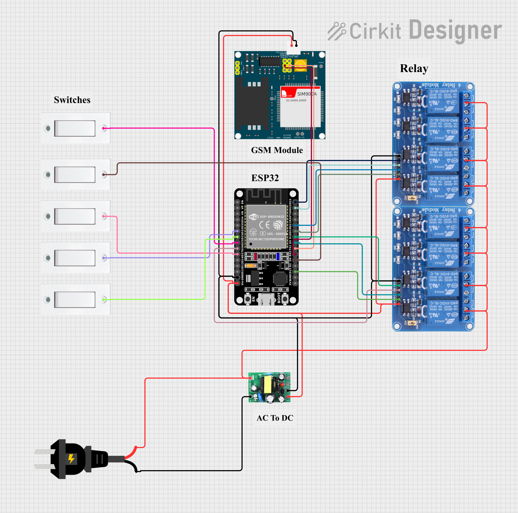
- Home automation and IoT devices
Technical Specifications
Below are the general technical specifications for a typical Relais MOSFET. Note that specific values may vary depending on the exact model.
| Parameter | Value |
|---|---|
| Operating Voltage | 3.3V to 24V (control signal) |
| Load Voltage Range | Up to 100V (depending on model) |
| Load Current Range | Up to 30A (depending on model) |
| On-State Resistance (Rds) | Typically < 0.1Ω |
| Switching Speed | < 1µs (on/off) |
| Isolation | Optocoupler or galvanic isolation |
| Operating Temperature | -40°C to +125°C |
Pin Configuration and Descriptions
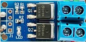
The Relais MOSFET typically has a 4-pin or 6-pin configuration. Below is a description of the common pinout:
4-Pin Configuration
| Pin | Name | Description |
|---|---|---|
| 1 | V+ (Control) | Positive control signal input (3.3V to 24V). |
| 2 | GND (Control) | Ground connection for the control signal. |
| 3 | Drain (Load) | Connect to the positive terminal of the load. |
| 4 | Source (Load) | Connect to the negative terminal of the load or ground. |
6-Pin Configuration (with Isolation)
| Pin | Name | Description |
|---|---|---|
| 1 | V+ (Control) | Positive control signal input (3.3V to 24V). |
| 2 | GND (Control) | Ground connection for the control signal. |
| 3 | Opto+ | Positive terminal of the optocoupler (for isolation). |
| 4 | Opto- | Negative terminal of the optocoupler (for isolation). |
| 5 | Drain (Load) | Connect to the positive terminal of the load. |
| 6 | Source (Load) | Connect to the negative terminal of the load or ground. |
Usage Instructions
How to Use the Component in a Circuit
Connect the Control Signal:
- Attach the control signal (e.g., from a microcontroller like Arduino) to the
V+pin. - Connect the
GNDpin to the ground of the control circuit.
- Attach the control signal (e.g., from a microcontroller like Arduino) to the
Connect the Load:
- Connect the positive terminal of the load to the
Drainpin. - Connect the negative terminal of the load to the
Sourcepin or ground.
- Connect the positive terminal of the load to the
Power the Circuit:
- Ensure the control signal voltage is within the operating range of the MOSFET relay.
- Apply the appropriate load voltage to the circuit.
Switching:
- When the control signal is applied, the MOSFET relay will switch on, allowing current to flow through the load.
- Removing the control signal will turn the relay off, stopping the current flow.
Important Considerations and Best Practices
- Heat Dissipation: Ensure proper heat dissipation for high-current loads by using a heatsink or cooling mechanism.
- Voltage Spikes: Use a flyback diode across inductive loads (e.g., motors) to protect the MOSFET from voltage spikes.
- Isolation: If the relay includes an optocoupler, ensure proper isolation between the control and load circuits.
- Gate Resistor: Use a small resistor (e.g., 100Ω) in series with the control signal to limit inrush current to the MOSFET gate.
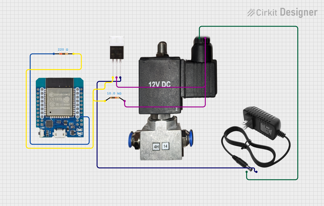
Example: Using a Relais MOSFET with Arduino UNO
Below is an example of how to control a 12V LED strip using a Relais MOSFET and an Arduino UNO.
Circuit Diagram
- Connect the
V+pin of the MOSFET relay to an Arduino digital pin (e.g., D9). - Connect the
GNDpin of the relay to the Arduino ground. - Connect the
Drainpin to the positive terminal of the LED strip. - Connect the
Sourcepin to the ground of the LED strip.
Arduino Code
// Define the MOSFET relay control pin
const int relayPin = 9;

void setup() {
  // Set the relay pin as an output
  pinMode(relayPin, OUTPUT);
}

void loop() {
  // Turn the relay on (LED strip on)
  digitalWrite(relayPin, HIGH);
  delay(1000); // Keep it on for 1 second

  // Turn the relay off (LED strip off)
  digitalWrite(relayPin, LOW);
  delay(1000); // Keep it off for 1 second
}
Troubleshooting and FAQs
Common Issues and Solutions
The relay does not switch on:
- Cause: Insufficient control signal voltage.
- Solution: Verify that the control signal voltage is within the operating range (3.3V to 24V).
The load does not turn off completely:
- Cause: Leakage current through the MOSFET.
- Solution: Check the MOSFET's specifications for leakage current and ensure it is suitable for your application.
Excessive heating of the MOSFET:
- Cause: High load current or poor heat dissipation.
- Solution: Use a heatsink or cooling fan to manage heat dissipation.
Voltage spikes damage the MOSFET:
- Cause: Inductive load without protection.
- Solution: Add a flyback diode across the load to suppress voltage spikes.
FAQs
Q: Can I use a Relais MOSFET with a 5V microcontroller?
A: Yes, most Relais MOSFETs are compatible with 5V control signals. However, verify the specific model's control voltage range.
Q: Is a heatsink always necessary?
A: A heatsink is only required for high-current loads or when the MOSFET operates near its maximum power rating.
Q: Can I use a Relais MOSFET for AC loads?
A: No, standard MOSFET relays are designed for DC loads. For AC loads, use a solid-state relay (SSR) or a TRIAC-based solution.