How to Use R4 minima: Examples, Pinouts, and Specs

Introduction
The R4 Minima is a resistor designed to limit current flow in electronic circuits. It provides a minimum resistance value, ensuring the proper operation and protection of components in the circuit. Resistors like the R4 Minima are essential in controlling voltage levels, dividing voltages, and protecting sensitive components from excessive current.
Explore Projects Built with R4 minima
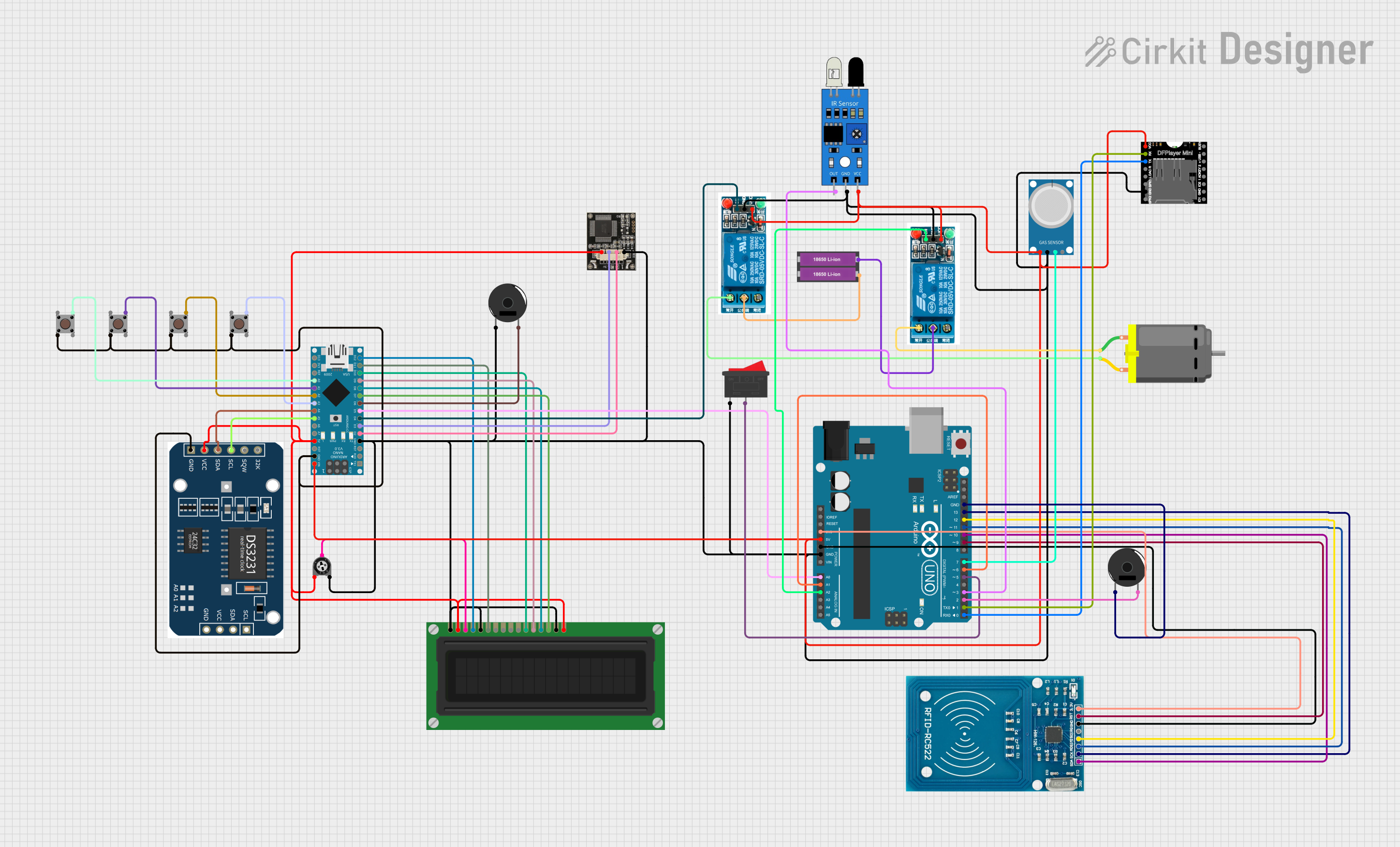
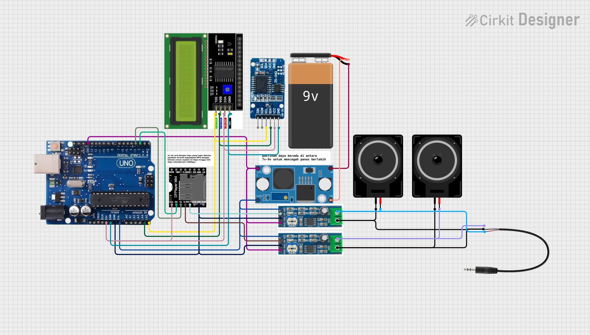
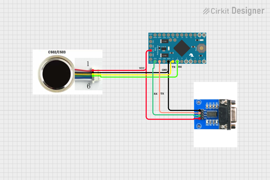

Explore Projects Built with R4 minima
Common Applications and Use Cases
- Current limiting in LED circuits
- Voltage division in sensor circuits
- Pull-up or pull-down resistors in digital circuits
- Protection of components from overcurrent
- Signal conditioning in analog circuits
Technical Specifications
The R4 Minima resistor is characterized by its resistance value, power rating, and tolerance. Below are the key technical details:
Key Specifications
| Parameter | Value |
|---|---|
| Resistance Value | 4 Ω (Ohms) |
| Power Rating | 0.25 W (1/4 Watt) |
| Tolerance | ±5% |
| Temperature Coefficient | ±200 ppm/°C |
| Maximum Voltage | 200 V |
| Operating Temperature Range | -55°C to +155°C |
Pin Configuration and Description
The R4 Minima is a two-terminal passive component. The pins are not polarized, meaning they can be connected in either orientation. Below is a description of the pins:
| Pin Number | Description |
|---|---|
| Pin 1 | Connects to one side of the circuit |
| Pin 2 | Connects to the other side of the circuit |
Usage Instructions
How to Use the R4 Minima in a Circuit
- Determine the Required Resistance: Ensure that the 4 Ω resistance value of the R4 Minima is suitable for your application. Use Ohm's Law (V = IR) to calculate the required resistance for your circuit.
- Insert the Resistor: Place the R4 Minima in the circuit, ensuring it is connected in series with the component you want to protect or limit current to.
- Solder the Resistor: If using a PCB, solder the resistor securely to the board. Ensure the solder joints are clean and free of shorts.
- Test the Circuit: Power on the circuit and measure the current or voltage to confirm the resistor is functioning as expected.
Important Considerations and Best Practices
- Power Dissipation: Ensure the resistor's power rating (0.25 W) is not exceeded. Calculate power dissipation using ( P = I^2R ) or ( P = V^2/R ).
- Tolerance: Account for the ±5% tolerance when designing precision circuits.
- Temperature Effects: Be aware of the temperature coefficient (±200 ppm/°C), which may affect resistance at extreme temperatures.
- Orientation: Since the R4 Minima is non-polarized, it can be connected in either direction.
Example: Using R4 Minima with an Arduino UNO
The R4 Minima can be used as a current-limiting resistor for an LED connected to an Arduino UNO. Below is an example circuit and code:
Circuit Description
- Connect one terminal of the R4 Minima to a digital pin (e.g., Pin 13) of the Arduino UNO.
- Connect the other terminal of the R4 Minima to the anode (+) of the LED.
- Connect the cathode (-) of the LED to the GND pin of the Arduino.
Arduino Code
// This code blinks an LED connected to Pin 13 with the R4 Minima resistor
// as a current-limiting component.

const int ledPin = 13; // Pin connected to the LED

void setup() {
  pinMode(ledPin, OUTPUT); // Set the LED pin as an output
}

void loop() {
  digitalWrite(ledPin, HIGH); // Turn the LED on
  delay(1000);                // Wait for 1 second
  digitalWrite(ledPin, LOW);  // Turn the LED off
  delay(1000);                // Wait for 1 second
}
Troubleshooting and FAQs
Common Issues and Solutions
LED Does Not Light Up
- Cause: Incorrect resistor value or loose connections.
- Solution: Verify the resistor value is 4 Ω and check all connections.
Resistor Overheats
- Cause: Exceeding the power rating of the resistor.
- Solution: Ensure the current and voltage through the resistor do not exceed its power rating (0.25 W).
Circuit Malfunctions
- Cause: Incorrect placement of the resistor.
- Solution: Ensure the resistor is connected in series with the component it is protecting.
FAQs
Q: Can I use the R4 Minima in high-power circuits?
A: No, the R4 Minima is rated for 0.25 W. For high-power circuits, use a resistor with a higher power rating.
Q: Does the orientation of the R4 Minima matter?
A: No, the R4 Minima is non-polarized and can be connected in either direction.
Q: How do I calculate the current through the R4 Minima?
A: Use Ohm's Law: ( I = V/R ), where ( V ) is the voltage across the resistor and ( R ) is its resistance (4 Ω).