
How to Use OPTO_DARL_6N138S: Examples, Pinouts, and Specs
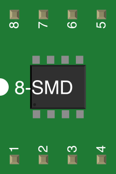
 Design with OPTO_DARL_6N138S in Cirkit Designer
Introduction
The 6N138 optocoupler, manufactured by Vishay Semiconductors, is a high-performance component designed to provide electrical isolation between input and output circuits. It achieves this by utilizing a gallium arsenide infrared LED and a photodetector. This design allows for signal transmission without any direct electrical connection, ensuring safety and noise immunity.
Explore Projects Built with OPTO_DARL_6N138S
 Open Project in Cirkit Designer
 Open Project in Cirkit Designer
 Open Project in Cirkit Designer
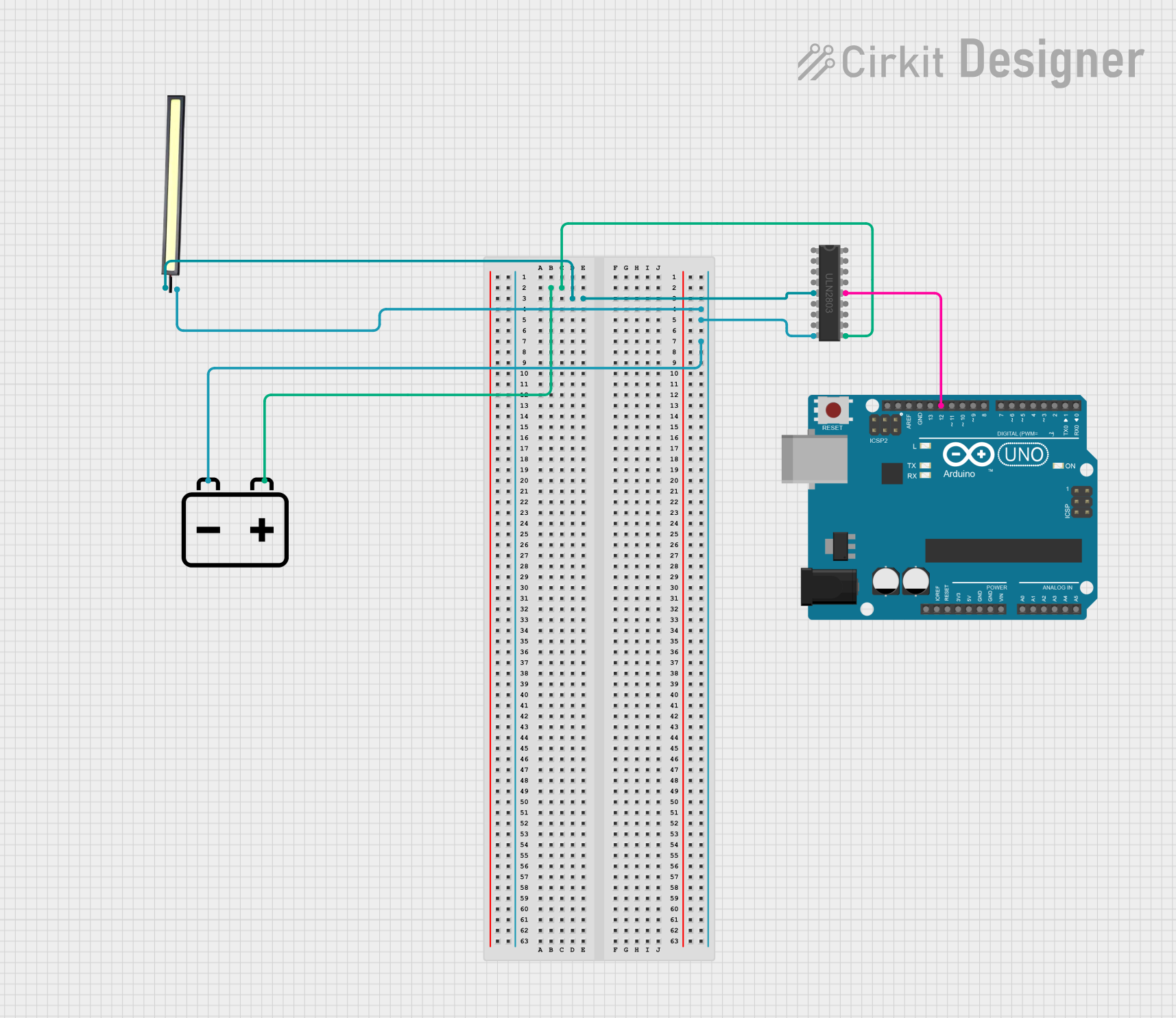 Open Project in Cirkit Designer
Explore Projects Built with OPTO_DARL_6N138S
Open Project in Cirkit DesignerOpen Project in Cirkit DesignerOpen Project in Cirkit DesignerOpen Project in Cirkit DesignerCommon Applications and Use Cases
- High-speed data communication
- Microcontroller interfacing
- Signal isolation in industrial systems
- Noise suppression in sensitive circuits
- Protection of low-voltage circuits from high-voltage transients
Technical Specifications
The following table outlines the key technical details of the 6N138 optocoupler:
| Parameter | Value |
|---|---|
| Input LED Forward Voltage | 1.2 V (typical), 1.5 V (maximum) |
| Input LED Forward Current | 10 mA (typical), 20 mA (maximum) |
| Output Collector-Emitter Voltage | 30 V (maximum) |
| Current Transfer Ratio (CTR) | 300% to 600% |
| Isolation Voltage | 5000 Vrms |
| Propagation Delay (High to Low) | 2 µs (typical) |
| Operating Temperature Range | -55°C to +100°C |
| Package Type | DIP-8 or SMD-8 |
Pin Configuration and Descriptions
The 6N138 is available in an 8-pin DIP or SMD package. The pinout is as follows:
| Pin Number | Name | Description |
|---|---|---|
| 1 | Anode | Positive terminal of the input LED. Connect to the input signal. |
| 2 | Cathode | Negative terminal of the input LED. Connect to ground or a current-limiting resistor. |
| 3 | NC (No Connect) | Not connected internally. Leave unconnected or use as a mechanical support. |
| 4 | Emitter (E) | Emitter of the phototransistor. Connect to ground or load. |
| 5 | Collector (C) | Collector of the phototransistor. Connect to the output circuit. |
| 6 | Vcc | Positive supply voltage for the output side. |
| 7 | Base | Base of the phototransistor. Typically left unconnected or used for biasing. |
| 8 | NC (No Connect) | Not connected internally. Leave unconnected or use as a mechanical support. |
Usage Instructions
How to Use the 6N138 in a Circuit
Input Side (LED):
- Connect the anode (Pin 1) to the input signal through a current-limiting resistor.
- Connect the cathode (Pin 2) to ground.
- Choose the resistor value to limit the LED current to a safe level (e.g., 10 mA).
Output Side (Phototransistor):
- Connect the collector (Pin 5) to the positive supply voltage (Vcc) through a pull-up resistor.
- Connect the emitter (Pin 4) to ground.
- The output signal can be read at the collector (Pin 5).
Power Supply:
- Provide a stable supply voltage (typically 5 V) to the Vcc pin (Pin 6).
Optional Base Connection:
- If needed, connect the base (Pin 7) to a biasing resistor or leave it unconnected.
Important Considerations and Best Practices
- Ensure the input LED current does not exceed the maximum rating of 20 mA.
- Use a pull-up resistor on the output side to ensure proper signal levels.
- Maintain proper isolation distances on the PCB to maximize the isolation voltage.
- Avoid exposing the component to temperatures beyond its operating range (-55°C to +100°C).
Example: Interfacing with an Arduino UNO
The following example demonstrates how to use the 6N138 to isolate a digital input signal for an Arduino UNO:
// Example: Using 6N138 Optocoupler with Arduino UNO
// This code reads a digital signal from the optocoupler and toggles an LED.

const int optoInputPin = 2;  // Pin connected to the optocoupler output
const int ledPin = 13;       // Built-in LED on Arduino UNO

void setup() {
  pinMode(optoInputPin, INPUT);  // Set optocoupler output pin as input
  pinMode(ledPin, OUTPUT);       // Set LED pin as output
}

void loop() {
  int signal = digitalRead(optoInputPin);  // Read the optocoupler output
  digitalWrite(ledPin, signal);           // Reflect the signal on the LED
}
Note: Ensure the pull-up resistor is connected to the optocoupler's output pin to provide a valid logic level for the Arduino.
Troubleshooting and FAQs
Common Issues and Solutions
No Output Signal:
- Verify the input LED is receiving sufficient current. Check the current-limiting resistor value.
- Ensure the pull-up resistor is correctly connected on the output side.
Output Signal is Weak or Unstable:
- Check the power supply voltage and ensure it is stable.
- Verify the pull-up resistor value. A typical value is 10 kΩ, but it may need adjustment based on the circuit.
Excessive Heat or Component Damage:
- Ensure the input current and output voltage do not exceed the maximum ratings.
- Check for short circuits or incorrect wiring.
FAQs
Q: Can the 6N138 be used for analog signal isolation?
A: The 6N138 is primarily designed for digital signal isolation. While it can handle some analog signals, its performance may degrade for high-frequency or precision analog applications.
Q: What is the maximum data rate supported by the 6N138?
A: The 6N138 supports data rates up to approximately 100 kHz, making it suitable for many high-speed digital applications.
Q: Can I use the 6N138 with a 3.3 V system?
A: Yes, the 6N138 can operate with a 3.3 V supply, but ensure the input LED current and output pull-up resistor are appropriately adjusted for the lower voltage.
By following this documentation, users can effectively integrate the 6N138 optocoupler into their designs for reliable signal isolation and noise immunity.