How to Use DC Gear Motor (3-6V): Examples, Pinouts, and Specs
Introduction
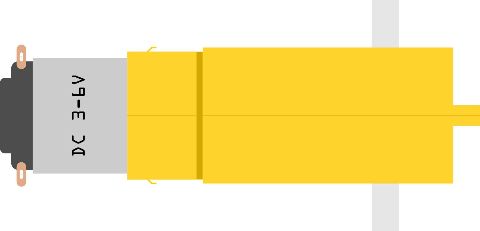
A DC gear motor is an electric motor that converts direct current (DC) electrical energy into mechanical energy. It features an integrated gear mechanism that reduces the motor's speed while increasing its torque. This makes it ideal for applications requiring precise control of rotational speed and high torque output. The DC gear motor operates efficiently within a voltage range of 3 to 6 volts, making it suitable for low-power applications.
Explore Projects Built with DC Gear Motor (3-6V)
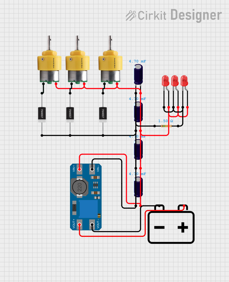
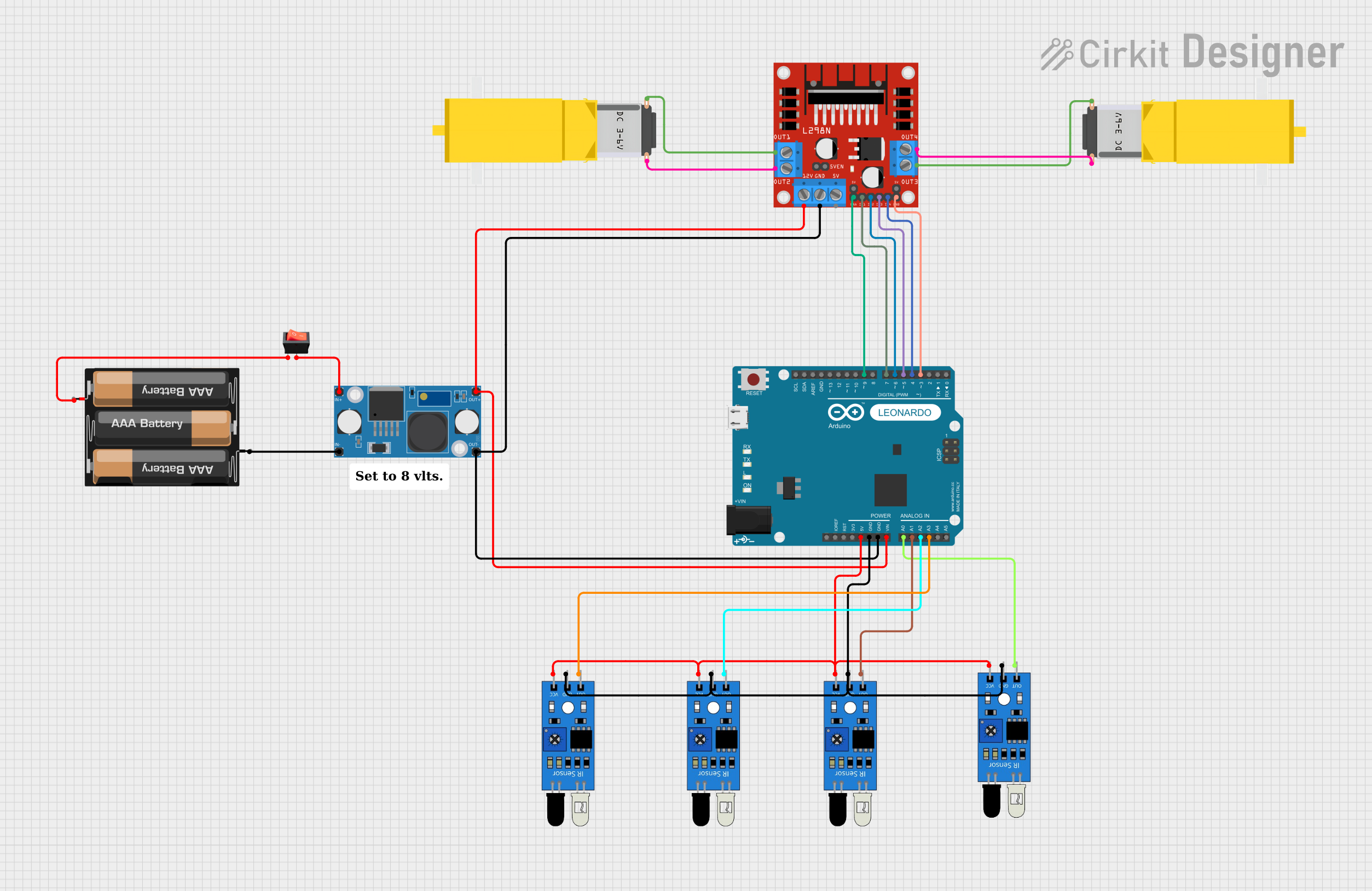


Explore Projects Built with DC Gear Motor (3-6V)
Common Applications and Use Cases
- Robotics: Driving wheels, arms, or other moving parts.
- Automated systems: Conveyor belts, small actuators, or mechanisms.
- DIY projects: Model cars, boats, or other hobbyist creations.
- Educational purposes: Demonstrating motor control and gear reduction principles.
Technical Specifications
Below are the key technical details of the DC gear motor (3-6V):
| Parameter | Value |
|---|---|
| Operating Voltage | 3V to 6V |
| Rated Torque | 0.5 kg·cm to 1.5 kg·cm (varies) |
| No-Load Speed | 100 RPM to 300 RPM (varies) |
| Stall Current | ~1.2A (at 6V) |
| Gear Ratio | Typically 1:48 or 1:120 |
| Shaft Diameter | 3 mm |
| Motor Dimensions | ~25 mm x 20 mm x 15 mm |
| Weight | ~30 g |
Pin Configuration and Descriptions
The DC gear motor typically has two terminals for electrical connections:
| Pin | Description |
|---|---|
| + | Positive terminal for power input (3-6V DC). |
| - | Negative terminal for ground connection. |
Usage Instructions
How to Use the Component in a Circuit
- Power Supply: Connect the motor's terminals to a DC power source within the 3-6V range. Ensure the power supply can provide sufficient current (e.g., 1.2A for stall conditions).
- Polarity Control: Reversing the polarity of the connections will reverse the motor's rotation direction.
- Motor Driver: For precise control, use a motor driver (e.g., L298N or L293D) to interface the motor with a microcontroller like an Arduino.
- Mounting: Secure the motor using screws or a motor mount to prevent movement during operation.
Important Considerations and Best Practices
- Voltage Range: Do not exceed the 6V maximum operating voltage to avoid damaging the motor.
- Current Handling: Ensure your power supply or motor driver can handle the stall current to prevent overheating or failure.
- Load Management: Avoid overloading the motor, as excessive torque demands can cause stalling or damage.
- Heat Dissipation: Prolonged operation at high loads may cause the motor to heat up. Allow for cooling periods if necessary.
Example: Connecting to an Arduino UNO
Below is an example of controlling a DC gear motor using an Arduino UNO and an L298N motor driver:
// Example: Controlling a DC Gear Motor with Arduino UNO and L298N Motor Driver

// Define motor control pins
const int motorPin1 = 9; // IN1 on L298N
const int motorPin2 = 10; // IN2 on L298N
const int enablePin = 11; // ENA on L298N (PWM control)

void setup() {
  // Set motor pins as outputs
  pinMode(motorPin1, OUTPUT);
  pinMode(motorPin2, OUTPUT);
  pinMode(enablePin, OUTPUT);
}

void loop() {
  // Rotate motor forward
  digitalWrite(motorPin1, HIGH); // Set IN1 high
  digitalWrite(motorPin2, LOW);  // Set IN2 low
  analogWrite(enablePin, 128);   // Set speed (0-255, 128 = ~50% speed)
  delay(2000);                   // Run for 2 seconds

  // Stop motor
  digitalWrite(motorPin1, LOW);
  digitalWrite(motorPin2, LOW);
  delay(1000);                   // Pause for 1 second

  // Rotate motor backward
  digitalWrite(motorPin1, LOW);  // Set IN1 low
  digitalWrite(motorPin2, HIGH); // Set IN2 high
  analogWrite(enablePin, 128);   // Set speed (0-255, 128 = ~50% speed)
  delay(2000);                   // Run for 2 seconds

  // Stop motor
  digitalWrite(motorPin1, LOW);
  digitalWrite(motorPin2, LOW);
  delay(1000);                   // Pause for 1 second
}
Notes:
- Connect the motor's terminals to the L298N's output pins (OUT1 and OUT2).
- Ensure the L298N is powered with a suitable voltage (e.g., 6V) and has a common ground with the Arduino.
Troubleshooting and FAQs
Common Issues and Solutions
Motor Not Spinning:
- Check the power supply voltage and current. Ensure it meets the motor's requirements.
- Verify all connections, especially polarity and motor driver wiring.
- Test the motor directly with a power supply to rule out driver or code issues.
Motor Overheating:
- Reduce the load on the motor or ensure it is not stalled.
- Operate the motor within its rated voltage and current limits.
Inconsistent Speed:
- Check for loose connections or insufficient power supply.
- Use a motor driver with PWM control for smoother speed regulation.
Noisy Operation:
- Inspect the motor for debris or damage to the gears.
- Apply lubrication to the gear mechanism if necessary.
FAQs
Q: Can I power the motor directly from an Arduino pin?
A: No, the Arduino pins cannot supply enough current to drive the motor. Use a motor driver or external power supply.
Q: How do I reverse the motor's direction?
A: Swap the polarity of the motor's terminals or use a motor driver to control the direction programmatically.
Q: What happens if I exceed the 6V limit?
A: Exceeding the voltage limit can damage the motor's windings or cause overheating. Always stay within the specified range.
Q: Can I use this motor for high-speed applications?
A: No, DC gear motors are designed for low-speed, high-torque applications. For high-speed needs, consider a standard DC motor without a gearbox.