How to Use ADXL 335: Examples, Pinouts, and Specs
ADXL 335 Documentation
1. Introduction
The ADXL 335 is a small, thin, low-power, 3-axis accelerometer manufactured by Analog Devices. It is designed to measure acceleration with high resolution (up to 13 bits) and can detect both static acceleration (e.g., gravity) and dynamic acceleration (e.g., motion or vibration). The device is ideal for applications requiring precise motion sensing and tilt detection.
Common Applications:
- Motion sensing in mobile devices
- Tilt detection in gaming controllers
- Vibration monitoring in industrial equipment
- Robotics and drone navigation
- Wearable devices for activity tracking
The ADXL 335 is easy to interface with microcontrollers like the Arduino UNO, making it a popular choice for hobbyists and professionals alike.
2. Technical Specifications
The following table outlines the key technical details of the ADXL 335:
| Parameter | Value |
|---|---|
| Supply Voltage (VCC) | 1.8V to 3.6V |
| Typical Operating Voltage | 3.3V |
| Current Consumption | 350 µA (typical) |
| Measurement Range | ±3g |
| Sensitivity | 300 mV/g |
| Output Type | Analog |
| Bandwidth (X, Y, Z axes) | 0.5 Hz to 1600 Hz (adjustable) |
| Operating Temperature Range | -40°C to +85°C |
| Dimensions | 4 mm × 4 mm × 1.45 mm (LFCSP) |
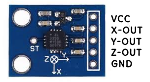
Pin Configuration and Descriptions
The ADXL 335 has a total of 5 pins. The pinout and their descriptions are as follows:
| Pin Name | Pin Number | Description |
|---|---|---|
| VCC | 1 | Power supply input (1.8V to 3.6V) |
| GND | 2 | Ground connection |
| XOUT | 3 | Analog output for X-axis acceleration |
| YOUT | 4 | Analog output for Y-axis acceleration |
| ZOUT | 5 | Analog output for Z-axis acceleration |
3. Usage Instructions
Connecting the ADXL 335 to an Arduino UNO
The ADXL 335 outputs analog signals for the X, Y, and Z axes, which can be read using the Arduino's analog input pins. Below is a typical wiring setup:
| ADXL 335 Pin | Arduino UNO Pin |
|---|---|
| VCC | 3.3V |
| GND | GND |
| XOUT | A0 |
| YOUT | A1 |
| ZOUT | A2 |
Sample Arduino Code
The following Arduino sketch reads the X, Y, and Z axis values from the ADXL 335 and prints them to the Serial Monitor.
// Define the analog pins connected to the ADXL 335
const int xPin = A0; // X-axis output
const int yPin = A1; // Y-axis output
const int zPin = A2; // Z-axis output

void setup() {
  Serial.begin(9600); // Initialize serial communication at 9600 baud
}

void loop() {
  // Read analog values from the ADXL 335
  int xValue = analogRead(xPin);
  int yValue = analogRead(yPin);
  int zValue = analogRead(zPin);

  // Convert the raw analog values to voltage (assuming 3.3V reference)
  float xVoltage = (xValue * 3.3) / 1023.0;
  float yVoltage = (yValue * 3.3) / 1023.0;
  float zVoltage = (zValue * 3.3) / 1023.0;

  // Print the voltage values to the Serial Monitor
  Serial.print("X Voltage: ");
  Serial.print(xVoltage);
  Serial.print(" V, Y Voltage: ");
  Serial.print(yVoltage);
  Serial.print(" V, Z Voltage: ");
  Serial.print(zVoltage);
  Serial.println(" V");

  delay(500); // Wait for 500ms before the next reading
}
Important Considerations:
- Power Supply: Ensure the ADXL 335 is powered with a voltage between 1.8V and 3.6V. Using a voltage higher than 3.6V may damage the device.
- Analog Reference Voltage: The Arduino's analog reference voltage (default 5V or 3.3V) must match the ADXL 335's supply voltage for accurate readings.
- Filtering Noise: Use external capacitors on the XOUT, YOUT, and ZOUT pins to filter high-frequency noise. A typical value is 0.1 µF.
4. Troubleshooting and FAQs
Common Issues and Solutions
| Issue | Possible Cause | Solution |
|---|---|---|
| No output or incorrect readings | Incorrect wiring or loose connections | Double-check the wiring and connections. |
| Output values are noisy or unstable | High-frequency noise interference | Add 0.1 µF capacitors to the output pins. |
| Readings are inconsistent or incorrect | Mismatched analog reference voltage | Ensure Arduino's AREF matches VCC. |
| Device overheating | Overvoltage on VCC pin | Use a regulated 3.3V power supply. |
Frequently Asked Questions (FAQs)
Can the ADXL 335 measure tilt angles?
- Yes, the ADXL 335 can measure tilt angles by analyzing the static acceleration due to gravity on the X, Y, and Z axes.
What is the maximum range of acceleration the ADXL 335 can measure?
- The ADXL 335 has a measurement range of ±3g.
How do I adjust the bandwidth of the ADXL 335?
- The bandwidth can be adjusted by adding capacitors to the XOUT, YOUT, and ZOUT pins. Refer to the datasheet for recommended capacitor values.
Can I use the ADXL 335 with a 5V microcontroller?
- Yes, but you must use a voltage regulator or level shifter to ensure the ADXL 335 operates within its 1.8V to 3.6V range.
5. Additional Resources
- ADXL 335 Datasheet (Analog Devices)
- Arduino UNO Documentation
- Filtering Techniques for Accelerometers
This documentation provides a comprehensive guide to using the ADXL 335. For further assistance, refer to the datasheet or contact Analog Devices' technical support.
Explore Projects Built with ADXL 335
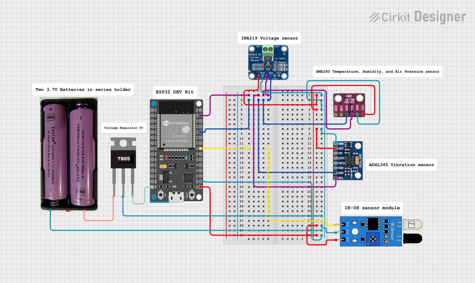


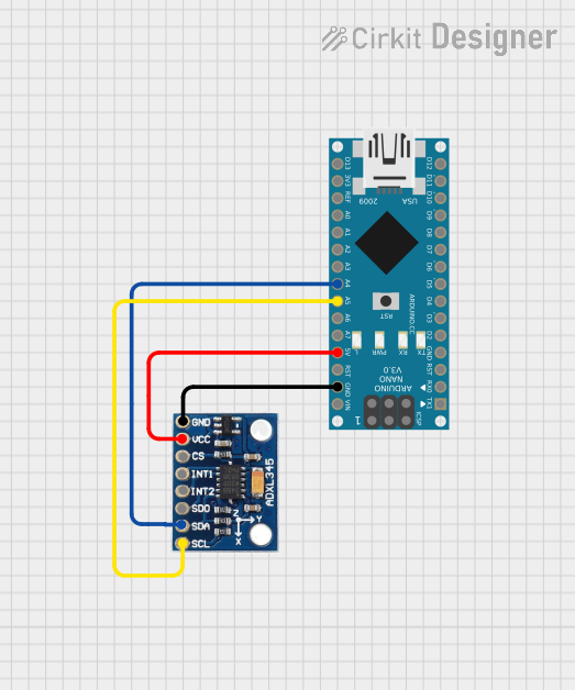
Explore Projects Built with ADXL 335