How to Use TP5000: Examples, Pinouts, and Specs
Introduction
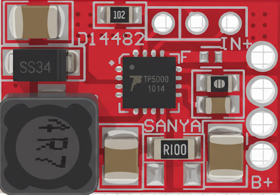
The TP5000 is a high-efficiency linear voltage regulator designed to provide a stable and reliable output voltage with a low dropout. It is widely used in power supply applications to maintain consistent voltage levels for sensitive electronic components. Its compact design and high performance make it an ideal choice for battery-powered devices, portable electronics, and embedded systems.
Explore Projects Built with TP5000


Explore Projects Built with TP5000
Common Applications and Use Cases
- Battery charging circuits
- Power supply regulation for microcontrollers and sensors
- Portable electronic devices
- Embedded systems requiring stable voltage
- Low-power IoT devices
Technical Specifications
The TP5000 is designed to deliver high efficiency and stable performance. Below are its key technical specifications:
| Parameter | Value |
|---|---|
| Input Voltage Range | 4.2V to 9V |
| Output Voltage | Configurable (e.g., 4.2V for Li-ion batteries) |
| Maximum Output Current | 2A |
| Dropout Voltage | < 0.2V at 1A load |
| Efficiency | Up to 90% |
| Operating Temperature | -40°C to +85°C |
| Package Type | SOP-8 |
Pin Configuration and Descriptions
The TP5000 comes in an SOP-8 package with the following pin configuration:
| Pin Number | Pin Name | Description |
|---|---|---|
| 1 | VIN | Input voltage pin. Connect to the power source. |
| 2 | GND | Ground pin. Connect to the circuit ground. |
| 3 | BAT | Battery connection pin. Connect to the battery's positive terminal. |
| 4 | STAT1 | Status indicator pin 1. Used for charge status indication. |
| 5 | STAT2 | Status indicator pin 2. Used for charge status indication. |
| 6 | NC | No connection. Leave unconnected or grounded. |
| 7 | VCC | Internal power supply pin. Connect to VIN. |
| 8 | PROG | Programming pin. Used to set the charging current. |
Usage Instructions
How to Use the TP5000 in a Circuit
- Power Input: Connect the VIN pin to a DC power source within the range of 4.2V to 9V.
- Battery Connection: Connect the BAT pin to the positive terminal of the battery. Ensure the battery type matches the configured output voltage (e.g., 4.2V for Li-ion).
- Grounding: Connect the GND pin to the circuit ground.
- Programming Charging Current: Use a resistor on the PROG pin to set the desired charging current. The resistor value can be calculated using the formula: [ I_{CHG} = \frac{1000}{R_{PROG}} ] where ( I_{CHG} ) is the charging current in mA, and ( R_{PROG} ) is the resistor value in kΩ.
- Status Indicators: Use the STAT1 and STAT2 pins to monitor the charging status. These pins can be connected to LEDs for visual indication.
Important Considerations and Best Practices
- Ensure the input voltage is within the specified range to avoid damaging the component.
- Use appropriate decoupling capacitors (e.g., 10µF) on the VIN and BAT pins to stabilize the voltage and reduce noise.
- Avoid exceeding the maximum output current of 2A to prevent overheating.
- Place the TP5000 and associated components on a well-designed PCB with proper thermal management to ensure efficient heat dissipation.
Example: Connecting TP5000 to an Arduino UNO
The TP5000 can be used to power an Arduino UNO by providing a stable 5V output. Below is an example of how to connect the TP5000 to an Arduino UNO:
- Connect the VIN pin of the TP5000 to a 6V DC power source.
- Connect the BAT pin to the 5V pin of the Arduino UNO.
- Connect the GND pin of the TP5000 to the GND pin of the Arduino UNO.
Here is an example Arduino code to monitor the charging status using the STAT1 pin:
// Define the STAT1 pin connected to the Arduino
const int stat1Pin = 2;

void setup() {
  pinMode(stat1Pin, INPUT); // Set STAT1 pin as input
  Serial.begin(9600);       // Initialize serial communication
}

void loop() {
  int stat1State = digitalRead(stat1Pin); // Read the STAT1 pin state

  if (stat1State == HIGH) {
    Serial.println("Battery is charging...");
  } else {
    Serial.println("Battery is fully charged or no battery connected.");
  }

  delay(1000); // Wait for 1 second before checking again
}
Troubleshooting and FAQs
Common Issues and Solutions
Component Overheating
- Cause: Excessive current draw or insufficient heat dissipation.
- Solution: Ensure the load does not exceed 2A. Use a heatsink or improve PCB thermal design.
No Output Voltage
- Cause: Incorrect wiring or insufficient input voltage.
- Solution: Verify all connections and ensure the input voltage is within the specified range.
LED Indicators Not Working
- Cause: Incorrect connection of STAT1/STAT2 pins or faulty LEDs.
- Solution: Check the wiring and replace the LEDs if necessary.
Battery Not Charging
- Cause: Incorrect programming resistor or incompatible battery type.
- Solution: Verify the resistor value on the PROG pin and ensure the battery matches the configured output voltage.
FAQs
Q1: Can the TP5000 charge multiple batteries in series?
A1: No, the TP5000 is designed to charge a single-cell battery. For multiple cells, use a dedicated multi-cell charger IC.
Q2: What happens if the input voltage exceeds 9V?
A2: Exceeding the input voltage range can damage the TP5000. Always use a regulated power source within the specified range.
Q3: Can I use the TP5000 for non-battery applications?
A3: Yes, the TP5000 can be used as a voltage regulator for low-power applications, provided the load does not exceed 2A.
Q4: How do I calculate the resistor value for a specific charging current?
A4: Use the formula ( R_{PROG} = \frac{1000}{I_{CHG}} ), where ( I_{CHG} ) is the desired charging current in mA. For example, for a 1A charging current, ( R_{PROG} = 1kΩ ).